Nissan Maxima Service and Repair Manual: P0715 input speed sensor A
Description
The primary speed sensor detects the primary pulley revolution speed and sends a signal to the TCM.
DTC Logic
DTC DETECTION LOGIC
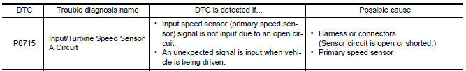
DTC CONFIRMATION PROCEDURE
CAUTION: Always drive vehicle at a safe speed.
NOTE: Immediately after performing any "DTC CONFIRMATION PROCEDURE", always turn ignition switch OFF.
Then wait at least 10 seconds before performing the next test.
1.CHECK DTC DETECTION
 With CONSULT
- Turn ignition switch ON.
- Select "Data Monitor" in "TRANSMISSION".
- Start engine and maintain the following conditions for at least 5 consecutive seconds.
 With GST
Follow the procedure "With CONSULT".
Diagnosis Procedure
Regarding Wiring Diagram information, refer to TM-126, "Wiring Diagram".
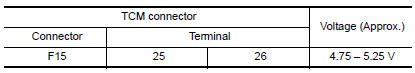
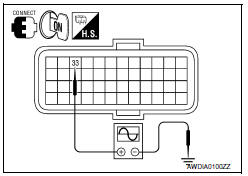
1.CHECK PRIMARY SPEED SENSOR
- Start engine.
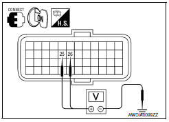
- Check voltage between TCM connector terminals.
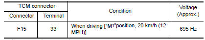
3. If OK, check the pulse when vehicle drive.
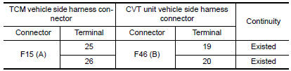
2. CHECK HARNESS BETWEEN TCM AND CVT UNIT HARNESS CONNECTOR (SENSOR POWER AND SENSOR GROUND) (PART 1)
- Turn ignition switch OFF.
- Disconnect TCM connector and CVT unit connector.
- Check continuity between TCM vehicle side harness connector terminals and CVT unit vehicle side harness connector terminals.
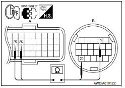
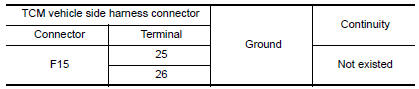
3. CHECK HARNESS BETWEEN TCM AND CVT UNIT HARNESS CONNECTOR (SENSOR POWER AND SENSOR GROUND) (PART 2)
Check continuity between TCM vehicle side harness connector terminals and ground.
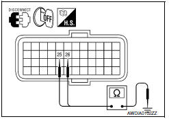
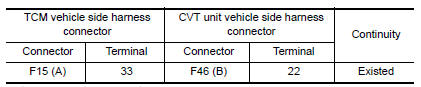
4. CHECK HARNESS BETWEEN TCM AND CVT UNIT HARNESS CONNECTOR (PRIMARY SPEED SENSOR) (PART 1)
- Turn ignition switch OFF.
- Check continuity between TCM vehicle side harness connector terminal and CVT unit vehicle side harness connector terminal.
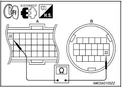
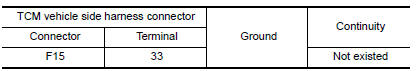
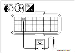
5. CHECK HARNESS BETWEEN TCM AND CVT UNIT HARNESS CONNECTOR (PRIMARY SPEED SENSOR) (PART 2)
Check continuity between TCM vehicle side harness connector terminal and ground.
6. CHECK THE TCM SHORT
- Replace with the same type of TCM. Refer to TM-168, "Exploded View".
- Connect each connectors.
- Perform "DTC CONFIRMATION PROCEDURE". Refer to TM-57, "DTC Logic".
7.DETECT MALFUNCTIONING ITEMS
Check TCM connector pin terminals for damage or loose connection with harness connector.
 P0710 transmission fluid temperature sensor A
Description
The CVT fluid temperature sensor detects the CVT fluid temperature and sends
a signal to the TCM.
DTC Logic
DTC DETECTION LOGIC
DTC CONFIRMATION PROCEDURE
CAUTION: Always drive ve ...
 P0720 output speed sensor
Description
The secondary speed sensor detects the revolution of the CVT output shaft and
emits a pulse signal. The
pulse signal is transmitted to the TCM, which converts it into vehicle speed.
...
Other materials:
The fuel gauge pointer does not move
Description
Fuel gauge needle will not move from a certain position.
Diagnosis Procedure
1.CHECK COMBINATION METER INPUT SIGNAL
Select "METER/M&A" on CONSULT.
Using "FUEL METER" of "DATA MONITOR", compare
the monitor value with the fuel gauge reading on
the co ...
Audio system
Symptom Table
AUDIO SYSTEM
RELATED TO HANDS-FREE PHONE
Before performing diagnosis, confirm that the cellular phone being
used by the customer is compatible with
the vehicle.
It is possible that a malfunction is occurring due to a version
change of the phone even tho ...
Heating (A/C OFF)
The air conditioner does not activate. When you
need to heat only, use this mode.
1. Press the AUTO button.
2. Turn the temperature control dial to set the
desired temperature.
The temperature of the passenger compartment
will be maintained automatically. Air
flow distribution and fa ...
Nissan Maxima Owners Manual
- Illustrated table of contents
- Safety-Seats, seat belts and supplemental restraint system
- Instruments and controls
- Pre-driving checks and adjustments
- Monitor, climate, audio, phone and voice recognition systems
- Starting and driving
- In case of emergency
- Appearance and care
- Do-it-yourself
- Maintenance and schedules
- Technical and consumer information
Nissan Maxima Service and Repair Manual

0.006