Nissan Maxima Service and Repair Manual: P0720 output speed sensor
Description
The secondary speed sensor detects the revolution of the CVT output shaft and emits a pulse signal. The pulse signal is transmitted to the TCM, which converts it into vehicle speed.
DTC Logic
DTC DETECTION LOGIC
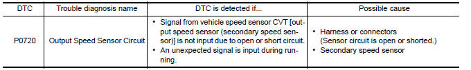
DTC CONFIRMATION PROCEDURE
CAUTION: Always drive vehicle at a safe speed.
NOTE: Immediately after performing any "DTC CONFIRMATION PROCEDURE", always turn ignition switch OFF.
Then wait at least 10 seconds before performing the next test.
1.CHECK DTC DETECTION
 With CONSULT
- Turn ignition switch ON.
- Select "Data Monitor" in "TRANSMISSION".
- Start engine and maintain the following conditions for at least 12 consecutive seconds.
ACC PEDAL OPEN : More than 1.0/8
RANGE : "D" position
Driving location : Driving the vehicle uphill (increased engine load) will help maintain the driving conditions required for this test.
 With GST
Follow the procedure "With CONSULT".
Diagnosis Procedure
Regarding Wiring Diagram information, refer to TM-126, "Wiring Diagram".
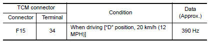
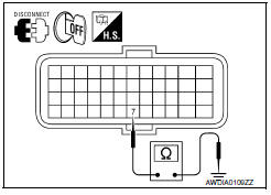
1.CHECK SECONDARY SPEED SENSOR
 With CONSULT
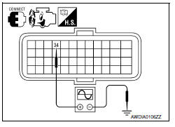
Check the pulse when vehicle drive.
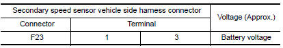
2.CHECK POWER AND SENSOR GROUND
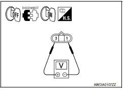
- Turn ignition switch OFF.
- Disconnect secondary speed sensor connector.
- Turn ignition switch ON.
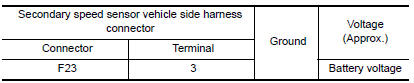
- Check voltage between secondary speed sensor vehicle side harness connector terminals.
5. Check voltage between secondary speed sensor vehicle side harness connector terminal and ground.
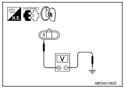
3.CHECK HARNESS BETWEEN TCM AND SECONDARY SPEED SENSOR (SENSOR GROUND)
-
Turn ignition switch OFF.
-
Disconnect TCM connector.
-
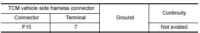
Check continuity between TCM vehicle side harness connector terminal and ground.
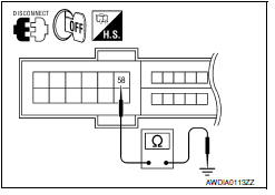
4.CHECK HARNESS BETWEEN TCM AND SECONDARY SPEED SENSOR (PART 1)
Check continuity between TCM vehicle side harness connector terminal and secondary speed sensor vehicle side harness connector terminal.
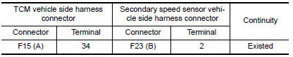
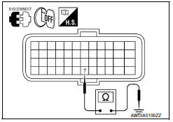
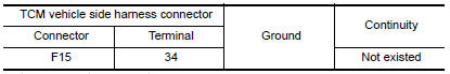
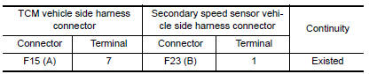
5.CHECK HARNESS BETWEEN TCM AND SECONDARY SPEED SENSOR (PART 2)
Check continuity between TCM vehicle side harness connector terminal and ground.
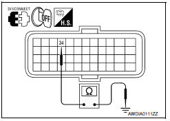
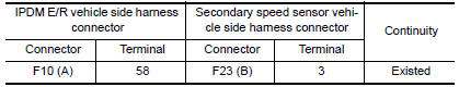
6.CHECK HARNESS BETWEEN IPDM E/R AND SECONDARY SPEED SENSOR (POWER) (PART 1)
- Turn ignition switch OFF.
- Disconnect IPDM E/R connector.
- Check continuity between IPDM E/R vehicle side harness connector terminal and secondary speed sensor vehicle side harness connector terminal.
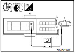
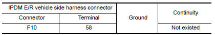
7.CHECK HARNESS BETWEEN IPDM E/R AND SECONDARY SPEED SENSOR (POWER) (PART 2)
Check continuity between IPDM E/R vehicle side harness connector terminal and ground.
8.CHECK HARNESS BETWEEN TCM AND SECONDARY SPEED SENSOR (SENSOR GROUND) (PART 1)
-
Turn ignition switch OFF.
-
Disconnect TCM connector.
-
Check continuity between TCM vehicle side harness connector terminal and secondary speed sensor vehicle side harness connector terminal.
9.CHECK HARNESS BETWEEN TCM AND SECONDARY SPEED SENSOR (SENSOR GROUND) (PART 2)
Check continuity between TCM vehicle side harness connector terminal and ground.
10.CHECK TCM
- Replace with the same type of TCM. Refer to TM-168, "Exploded View".
- Perform "DTC CONFIRMATION PROCEDURE". Refer to TM-60, "DTC Logic".
11.DETECT MALFUNCTIONING ITEMS
Check TCM connector pin terminals for damage or loose connection with harness connector.
 P0715 input speed sensor A
Description
The primary speed sensor detects the primary pulley revolution speed and
sends a signal to the TCM.
DTC Logic
DTC DETECTION LOGIC
DTC CONFIRMATION PROCEDURE
CAUTION:
Always driv ...
 P0725 engine speed
Description
The engine speed signal is transmitted from ECM to TCM via CAN communication
line.
DTC Logic
DTC DETECTION LOGIC
DTC CONFIRMATION PROCEDURE
CAUTION:
Always drive vehicle at a sa ...
Other materials:
Normal operating condition
Description
NOTE:
For Navigation system operation information, refer to Navigation system Owner's
Manual.
BASIC OPERATIONS
NOTE:
Locations stored in the Address Book and other memory functions may be lost if
the vehicle's battery is disconnected
or becomes discharged. If thi ...
GPS antenna
Removal and Installation
REMOVAL
Remove cluster lid A. Refer to IP-10, "Exploded View".
Remove the audio unit. Refer to AV-652, "Removal and
Installation".
Remove the GPS antenna screw (A).
- GPS antenna (1)
Detach the GPS antenna cable clip (A), then fish th ...
Precaution
PRECAUTIONS
Precaution for Supplemental Restraint System (SRS) "AIR BAG" and
"SEAT BELT PRE-TENSIONER"
The Supplemental Restraint System such as "AIR BAG" and "SEAT BELT
PRE-TENSIONER", used along with a front seat belt, helps to reduce the risk
or severity of injury to the driver and front ...
Nissan Maxima Owners Manual
- Illustrated table of contents
- Safety-Seats, seat belts and supplemental restraint system
- Instruments and controls
- Pre-driving checks and adjustments
- Monitor, climate, audio, phone and voice recognition systems
- Starting and driving
- In case of emergency
- Appearance and care
- Do-it-yourself
- Maintenance and schedules
- Technical and consumer information
Nissan Maxima Service and Repair Manual

0.0087