Nissan Maxima Service and Repair Manual: P0725 engine speed
Description
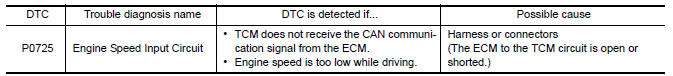
The engine speed signal is transmitted from ECM to TCM via CAN communication line.
DTC Logic
DTC DETECTION LOGIC
DTC CONFIRMATION PROCEDURE
CAUTION: Always drive vehicle at a safe speed.
NOTE: Immediately after performing any "DTC CONFIRMATION PROCEDURE", always turn ignition switch OFF.
Then wait at least 10 seconds before performing the next test.
1.CHECK DTC DETECTION
 With CONSULT
- Turn ignition switch ON.
- Select "Data Monitor" in "TRANSMISSION".
- Start engine and maintain the following conditions for at least 10 consecutive seconds.
Diagnosis Procedure
1.CHECK DTC WITH ECM
 With CONSULT
- Turn ignition switch ON.
- Perform "Self Diagnostic Results" in "ENGINE".
2.CHECK DTC WITH TCM
 With CONSULT
Perform "Self Diagnostic Results" in "TRANSMISSION".
3.DETECT MALFUNCTIONING ITEMS
Check TCM connector pin terminals for damage or loose connection with harness connector.
 P0720 output speed sensor
Description
The secondary speed sensor detects the revolution of the CVT output shaft and
emits a pulse signal. The
pulse signal is transmitted to the TCM, which converts it into vehicle speed.
...
 P0730 incorrect gear ratio
Description
TCM selects the gear ratio using the engine load (throttle position), the
primary pulley revolution speed, and
the secondary pulley revolution speed as input signals. Then it changes ...
Other materials:
P0128 thermostat function
DTC Logic
DTC DETECTION LOGIC
NOTE:
If DTC P0128 is displayed with DTC P0300, P0301, P0302, P0303, P0304, P0305 or
P0306, first perform
the trouble diagnosis for DTC P0300, P0301, P0302, P0303, P0304, P0305, P0306.
Engine coolant temperature has not risen enough to open the thermostat even ...
P1720 VSS
Description
ECM receives two vehicle speed signals via the CAN communication line. One is
sent from "ABS actuator and
electric unit (control unit)" via the combination meter, and the other is from
TCM (Transmission control module).
ECM uses these signals for engine control.
DTC Logic
DTC ...
Symptom diagnosis
SQUEAK AND RATTLE TROUBLE DIAGNOSES
Work Flow
CUSTOMER INTERVIEW
Interview the customer if possible, to determine the conditions that exist
when the noise occurs. Use the Diagnostic Worksheet during the interview to
document the facts and conditions when the noise occurs and any customer' ...
Nissan Maxima Owners Manual
- Illustrated table of contents
- Safety-Seats, seat belts and supplemental restraint system
- Instruments and controls
- Pre-driving checks and adjustments
- Monitor, climate, audio, phone and voice recognition systems
- Starting and driving
- In case of emergency
- Appearance and care
- Do-it-yourself
- Maintenance and schedules
- Technical and consumer information
Nissan Maxima Service and Repair Manual

0.0066