Nissan Maxima Service and Repair Manual: Water pump
Exploded View
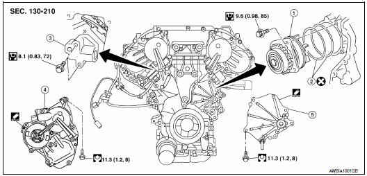
- Water pump
- O-rings
- Timing chain tensioner
- Intake valve timing control solenoid valve cover (RH) (bank 1)
- Water pump cover
Removal and Installation
WARNING: Do not remove the radiator cap when the engine is hot. Serious burns could occur from high pressure coolant escaping from the radiator. Wrap a thick cloth around the radiator cap. Slowly turn it a quarter turn to allow built-up pressure to escape. Carefully remove the radiator cap by turning it all the way.
CAUTION:
- When removing water pump assembly, be careful not to get coolant on drive belt.
- Water pump cannot be disassembled and should be replaced as a unit.
- After installing water pump, connect hose and clamp securely, then check for leaks using suitable tool.
NOTE: When removing components such as hoses, tubes/lines, etc., cap or plug openings to prevent fluid from spilling.
REMOVAL
- Drain engine coolant from the radiator. Refer to CO-11, "Changing
Engine Coolant".
CAUTION: Perform when the engine is cold. - Disconnect reservoir hose and remove reservoir tank.
- Remove RH wheel and tire using power tool. Refer to WT-60, "Adjustment".
- Remove the fender protector side cover (RH). Refer to EXT-23, "Exploded View".
- Set No. 1 cylinder at TDC on its compression stroke.
- Align pointer with TDC mark on crankshaft pulley.
- Remove drive belt. Refer to EM-14, "Removal and Installation".
- Remove the idler pulley and the A/C idler pulley. Refer to EM-15, "Removal and Installation of Drive Belt Auto-tensioner".
- Remove hoodledge cover (RH).
- Remove cylinder block front drain plug (1) on water pump side of cylinder block to drain engine coolant from engine.
- Support engine and remove the front engine insulator and bracket. Refer to EM-103, "Removal and Installation".
- Disconnect RH valve timing control harness connectors and remove Intake valve timing control solenoid valve cover (RH) (bank 1). Refer to EM-54, "Exploded View".
- Remove water pump cover. Refer to EM-54, "Exploded View".
- Remove the timing chain tensioner (primary) as follows:
- Pull the lever (C) down to release the plunger stopper tab (B).
- Insert the stopper pin A into the tensioner body hole to hold the lever (C) and keep the plunger stopper tab (B) released. NOTE: An allen wrench [1.2 mm (0.047 in)] is used for a stopper pin A as an example.
- Compress the plunger (D) into the tensioner body (1) by pressing the slack guide (2).
- Keep the slack guide (2) pressed and lock the plunger (D) in by pushing the stopper pin A through the lever (C) and into the chain tensioner body hole.
- Remove timing chain tensioner bolts and then remove the timing chain tensioner.
CAUTION: Be careful not to drop timing chain tensioner bolts inside timing chain case.
- Remove the three water pump bolts (A). Make a gap between water pump sprocket (1) and timing chain, by carefully turning crankshaft pulley (2) counterclockwise until timing chain loosens on water pump sprocket (1).
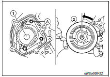
- Screw M8 bolts [pitch: 1.25 mm (0.49 in) length: approx. 50 mm (1.97 in)] into water pumps upper and lower bolt holes until they reach the timing chain case. Remove water pump.
CAUTION:
- Place a suitable shop cloth below the water pump housing to prevent any engine coolant from dripping into the timing chain case.
- Pull water pump straight out while preventing vane from contacting socket in installation area.
- Remove water pump without causing sprocket to contact timing chain.
- Remove M8 bolts and O-rings from water pump.
CAUTION: Do not reuse O-rings.
INSPECTION AFTER REMOVAL
- Visually check that there is no significant dirt or rusting on the water pump body and vane.
- Check that the vane shaft is not excessively loose and that it turns smoothly when rotated by hand.
- If the water pump does not perform properly, replace the water pump assembly.
INSTALLATION
- Install new O-rings to water pump.
CAUTION: Do not reuse O-rings. - Apply engine oil and coolant to the O-rings as shown.
- Locate the O-ring with white paint mark to engine front side.
- Hold timing chain to the side (
 ) and install the water pump
(
) and install the water pump
( ).
).
CAUTION: Do not allow cylinder block to interfere with the O-rings when installing the water pump.
- Check that timing chain and water pump sprocket are engaged.
- Tighten water pump bolts alternately and evenly to specification.
- Remove dust and foreign material completely from installation area of timing chain tensioner and rear timing chain case.
- Turn the crankshaft pulley approximately 20 clockwise so that the timing chain on the timing chain tensioner side is loose.
- Apply engine oil to the oil feed hole and timing chain tensioner and install the timing chain tensioner.
- Remove the stopper pin (A).
- Install intake valve timing control solenoid valve cover (RH) (bank 1) and water pump cover.
- Before installing, remove all traces of liquid
gasket from mating surface of water pump cover and intake
valve timing control solenoid valve cover (RH) (bank 1) using a scraper.
Also remove traces of liquid gasket from the mating surface of the front cover.
- Apply a continuous bead of liquid gasket to mating surface of intake valve timing control solenoid valve cover (RH) (bank 1) and water pump cover. Use Genuine RTV Silicone Sealant or equivalent. Refer to GI-21, "Recommended Chemical Products and Sealants".
- Install cylinder block front drain plug (1) on water pump side of cylinder block.
- Apply liquid gasket to the threads of cylinder block front drain plug.
Use Genuine RTV Silicone Sealant or equivalent. Refer to GI-21, "Recommended Chemical Products and Sealants".
Cylinder block front drain plug : 9.8 N*m (1.0 kg-m, 87 in-lb)
- Installation of remaining components is in the reverse order of removal.
- After installation refill engine coolant and check for leaks. Refer to
CO-11, "Changing Engine Coolant"
and CO-10, "System Inspection".
CAUTION: Do not spill coolant in engine compartment. Use a shop cloth to absorb coolant. - After starting engine, let idle for three minutes, then rev engine
up to 3,000 rpm under no load to purge
air from the high-pressure chamber of the chain tensioner. The engine may
produce a rattling noise.
This indicates that air still remains in the chamber and is not a matter of concern.
 Cooling fan
Removal and Installation
Radiator cooling fan assembly
WARNING:
Do not remove the radiator cap when the engine is hot. Serious burns could occur
from high pressure
coolant escaping from ...
 Thermostat and thermostat housing
Removal and Installation
Gasket
Thermostat assembly (water inlet)
WARNING:
Do not remove the radiator cap when the engine is hot. Serious burns could occur
from high pressure
engine ...
Other materials:
Heating (A/C OFF)
The air conditioner does not activate. When you
need to heat only, use this mode.
1. Press the AUTO button.
2. Turn the temperature control dial to set the
desired temperature.
The temperature of the passenger compartment
will be maintained automatically. Air
flow distribution and fa ...
P0451 evap control system pressure sensor
Description
The EVAP control system pressure sensor detects pressure in the
purge line. The sensor output voltage to the ECM increases as pressure
increases
DTC Logic
DTC DETECTION LOGIC
DTC CONFIRMATION PROCEDURE
NOTE:
Never remove fuel filler cap during DTC confirmation procedur ...
IPDM E/R (intelligent power distribution module engine room)
IPDM E/R (INTELLIGENT POWER DISTRIBUTION MODULE ENGINE
ROOM) : Diagnosis
Procedure
Regarding Wiring Diagram information, refer to PCS-28,
"Wiring Diagram".
1. CHECK FUSES AND FUSIBLE LINK
Check that the following IPDM E/R fuses or fusible link
are not blown.
2. CHECK POWER SUPPLY CIRCU ...
Nissan Maxima Owners Manual
- Illustrated table of contents
- Safety-Seats, seat belts and supplemental restraint system
- Instruments and controls
- Pre-driving checks and adjustments
- Monitor, climate, audio, phone and voice recognition systems
- Starting and driving
- In case of emergency
- Appearance and care
- Do-it-yourself
- Maintenance and schedules
- Technical and consumer information
Nissan Maxima Service and Repair Manual

0.0059