Nissan Maxima Service and Repair Manual: Intake door control system
System Diagram
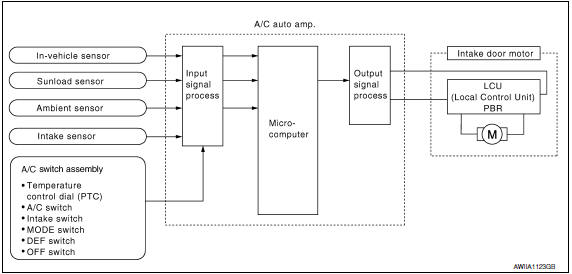
System Description
The intake doors are automatically controlled by the temperature setting, ambient temperature, in-vehicle temperature, intake temperature, amount of sunload and ON/OFF operation of the A/C compressor.
SYSTEM OPERATION
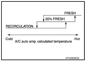
The intake door control judges intake door position based on the ambient temperature, the intake air temperature and the in-vehicle temperature. When in shifting mode position D/F, if the DEF or OFF switches are pressed, or when the A/C switch is OFF, the A/C auto amp. sets the intake door to the FRE position.
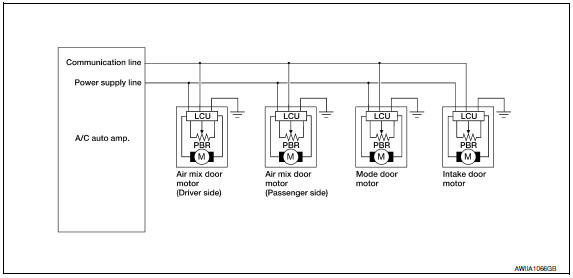
Door Motor Circuit
Intake Door Control Specification
 Air mix door control system
System Diagram
System Description
The air mix doors are automatically controlled so that in-vehicle temperature
is maintained at a predetermined
value by the temperature setting, ambient tem ...
 Blower motor control system
System Diagram
System Description
Fan speed is automatically controlled by the temperature setting, ambient
temperature, in-vehicle temperature,
intake temperature, amount of sunload and air ...
Other materials:
NISSAN Intelligent Key battery discharge
If the battery of the NISSAN Intelligent Key is
discharged, or environmental conditions interfere
with the Intelligent Key operation, start the engine
according to the following procedure:
1. Place the shift lever in the P (Park) position.
2. Firmly apply the foot brake.
3. Touch the i ...
U1000 CAN comm circuit
Description
CAN (Controller Area Network) is a serial communication line for real time
application. It is an on-vehicle multiplex communication line with high data
communication speed and excellent error detection ability. Many electronic
control units are equipped on a vehicle and each contr ...
Sunroof motor assembly
Wiring Diagram
...
Nissan Maxima Owners Manual
- Illustrated table of contents
- Safety-Seats, seat belts and supplemental restraint system
- Instruments and controls
- Pre-driving checks and adjustments
- Monitor, climate, audio, phone and voice recognition systems
- Starting and driving
- In case of emergency
- Appearance and care
- Do-it-yourself
- Maintenance and schedules
- Technical and consumer information
Nissan Maxima Service and Repair Manual

0.006