Nissan Maxima Service and Repair Manual: Multifunction switch
Removal and Installation
REMOVAL
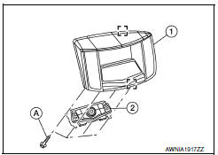
- Remove cluster lid D. Refer to IP-10, "Exploded View".
- Remove the four multifunction switch screws (A) and remove the
multifunction switch (2) from cluster lid D (1).
 : Metal clip
INSTALLATION
Installation is in the reverse order of removal.
 AV control unit
Removal and Installation
AV control unit
AV control unit bracket LH
AV control unit bracket RH
A/C auto amp.
Cluster lid C (with A/C and AV switch assembly attached)
Clip
AV C ...
 Audio display unit
Removal and Installation
Audio display unit bracket
Audio display unit
Cluster lid D
Multifunction switch
Audio display unit bracket screws
Audio display unit screws
Metal Cl ...
Other materials:
In-vehicle sensor
Removal and Installation
REMOVAL
Remove the instrument lower panel LH. Refer to IP-19, "Removal and
Installation".
Remove the in-vehicle sensor screw and the in-vehicle sensor.
INSTALLATION
Installation is in the reverse order of removal.
CAUTION:
Make sure that the asp ...
TCM branch line circuit
Diagnosis Procedure
1.CHECK CONNECTOR
Turn the ignition switch OFF.
Disconnect the battery cable from the negative terminal.
Check the following terminals and connectors for damage, bend and
loose connection (unit side and connector
side).
TCM
Harness connector F1
Harness con ...
Front power seat adjustment
Operating tips
The power seat motor has an auto-reset
overload protection circuit. If the motor
stops during operation, wait 30 seconds
then reactivate the switch.
Do not operate the power seat switch for a
long period of time when the engine is off.
This will discharge the bat ...
Nissan Maxima Owners Manual
- Illustrated table of contents
- Safety-Seats, seat belts and supplemental restraint system
- Instruments and controls
- Pre-driving checks and adjustments
- Monitor, climate, audio, phone and voice recognition systems
- Starting and driving
- In case of emergency
- Appearance and care
- Do-it-yourself
- Maintenance and schedules
- Technical and consumer information
Nissan Maxima Service and Repair Manual

0.0062