Nissan Maxima Service and Repair Manual: Intake Manifold
Removal and Installation
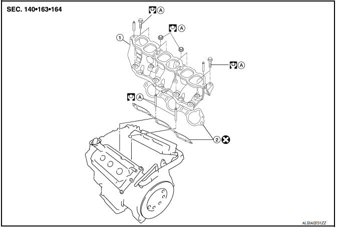
- Intake manifold
- Intake manifold gaskets
- Refer to INSTALLATION
REMOVAL
WARNING: To avoid the danger of being scalded, do not drain the coolant when the engine is hot.
- Release the fuel pressure. Refer to EC-592, "Inspection".
- Disconnect the battery negative terminal. Refer to PG-67, "Removal and Installation (Battery)".
- Remove intake manifold collector. Refer to EM-25, "Removal and Installation".
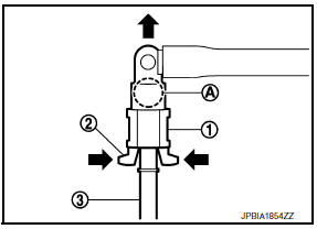
- Disconnect fuel tube quick connector at vehicle piping side.
- To remove the quick connector cap (1), hold the sides of the connector (A), push in the tabs (2) and pull out the fuel tube (3).
CAUTION:
- The tube can be removed when the tabs are completely depressed. Do not twist fuel tube.
- Do not use any tools to remove the quick connector.
- Keep the resin tube away from heat. Be especially careful when welding near the tube.
- Prevent acid liquids such as battery electrolyte, etc. from getting on the resin tube.
- Do not bend or twist the tube during removal or installation.
- Do not remove the remaining retainer on the tube.
- When the tube is replaced, also replace the retainer with a new one.
- To keep the connecting portion clean and to avoid damage and foreign materials entering, cover the ends of the fuel tubes with plastic bags or something similar.
NOTE: If the connector and the tube are stuck together, push and pull several times until they start to move. Then disconnect them by pulling.
- Remove the fuel rail with the fuel injectors attached, from the intake manifold. Remove the fuel injector O-rings and use new O-rings for installation.
CAUTION: Do not reuse O-rings.
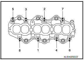
- Loosen the bolts in the order as shown, and remove the intake manifold with power tool.
INSPECTION AFTER REMOVAL
Surface Distortion
- Using straightedge and feeler gauge, inspect the surface distortion of the intake manifold.
Standard : 0.1 mm (0.004 in)
INSTALLATION
CAUTION: Do not reuse intake manifold gaskets.
Installation is in the reverse order of removal. Follow the procedure below for specific tightening sequences and procedures.
- Install intake manifold bolts in two steps in the numerical order as shown.
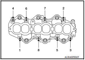
Step 1 : 7.4 N*m (0.75 kg-m, 65 in-lb)
Step 2 : 25.5 N*m (2.6 kg-m, 19
ft-lb)
NOTE: After installation, it is necessary to re-calibrate the electric throttle control actuator as follows:
- Perform the "Throttle Valve Closed Position Learning" when harness connector of the electric throttle control actuator is disconnected. Refer to EC-21, "THROTTLE VALVE CLOSED POSITION LEARNING : Special Repair Requirement".
- Perform the "Idle Air Volume Learning" when the electric throttle control actuator is replaced. Refer to EC- 21, "IDLE AIR VOLUME LEARNING : Special Repair Requirement".
- Install the quick connector as follows:
- Make sure no foreign substances are deposited in and around the fuel tube and quick connector and that there is no damage.
- Align the center to insert the quick connector straight onto the fuel tube.
- Insert the fuel tube until a click is heard.
- Install the quick connector cap on the quick connector joint. Align the arrow mark on the quick connector cap to the upper side.
- Install the fuel hose into the hose clamp.
INSPECTION AFTER INSTALLATION
Make sure there are no fuel leaks at connections as follows:
- Apply fuel pressure to fuel lines by turning ignition switch ON with engine stopped. Then check for fuel leaks at connections.
- Start the engine and rev it up and check for fuel leaks at connections.
CAUTION: Do not touch engine immediately after stopping as engine is extremely hot.
NOTE: Use mirrors for checking on connections out of the direct line of sight.
 Intake Manifold Collector
Removal and Installation
Intake manifold collector
Intake manifold collector gasket
Electric throttle control actuator gasket
Electric throttle control actuator
Refer to INSTALLATION ...
 Exhaust Manifold And Three Way Catalyst
Exploded View
Gasket
Exhaust manifold (RH)
Exhaust manifold heat shield (RH)
Air fuel ratio sensor 1 (bank 1)
Ring gasket
Three way catalyst (bank 1)
Three way catalyst support ( ...
Other materials:
Headlights
Replacing the halogen headlight bulb
(if so equipped)
The headlight is a semi-sealed beam type which
uses a replaceable headlight (halogen) bulb.
They can be replaced from inside the engine
compartment without removing the headlight assembly.
If headlight bulb replacement is required, it i ...
Push-button ignition switch illumination circuit
Description
Provides the power supply and the ground to control the push-button ignition
switch illumination.
Component Function Check
1.CHECK PUSH-BUTTON IGNITION SWITCH ILLUMINATION OPERATION
CONSULT
Turn the ignition switch ON.
Select "ENGINE SW ILLUMI" of BCM (INTELLGENT KEY) active ...
Diagnosis system (ipdm E/R)
Diagnosis Description
AUTO ACTIVE TEST
Description
In auto active test mode, the IPDM E/R sends a drive signal to the following
systems to check their operation.
Oil pressure warning lamp
Front wiper (LO, HI)
Parking lamps
Side marker lamps
License plate lamps
Tail lamps
Front f ...
Nissan Maxima Owners Manual
- Illustrated table of contents
- Safety-Seats, seat belts and supplemental restraint system
- Instruments and controls
- Pre-driving checks and adjustments
- Monitor, climate, audio, phone and voice recognition systems
- Starting and driving
- In case of emergency
- Appearance and care
- Do-it-yourself
- Maintenance and schedules
- Technical and consumer information
Nissan Maxima Service and Repair Manual

0.0059