Nissan Maxima Service and Repair Manual: Exhaust Manifold And Three Way Catalyst
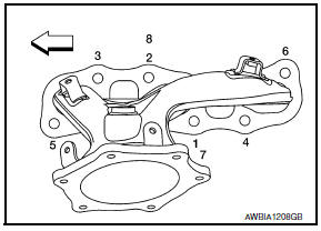
Exploded View
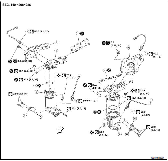
- Gasket
- Exhaust manifold (RH)
- Exhaust manifold heat shield (RH)
- Air fuel ratio sensor 1 (bank 1)
- Ring gasket
- Three way catalyst (bank 1)
- Three way catalyst support (bank 1)
- Heated oxygen sensor 2 (bank 1)
- Three way catalyst (bank 2)
- Three way catalyst support (bank 2)
- Heated oxygen sensor 2 (bank 2)
- Ring gasket
- Exhaust manifold (LH)
- Exhaust manifold heat shield (LH)
- Air fuel ratio sensor 1 (bank 2)
- To oil pan (upper)
- Upper mark
 Engine front
Removal and Installation (LH)
REMOVAL
WARNING:
- Perform the work when the exhaust system has completely cooled down.
- When removing the front and rear engine mounting through bolts and nuts, lift the engine up slightly for safety.
NOTE: When removing components such as hoses, tubes/lines, etc., cap or plug openings to prevent fluid from spilling.
- Remove the air cleaner case assembly, and air duct hose and resonator assembly. Refer to EM-24, "Removal and Installation".
- Remove the battery and battery tray assembly. Refer to PG-68, "Removal and Installation (Battery Tray)".
- Remove the radiator. Refer to CO-14, "Removal and Installation".
- Remove the fan shroud and fan motor. Refer to CO-16, "Removal and Installation".
- Remove the front exhaust tube. Refer to EX-5, "Exploded View".
- Remove the three way catalyst support brackets (LH).
- Remove heated oxygen sensor 2 (bank 2), air fuel ratio (A/F) sensor 1 (bank 2).
- . Remove harness connector of each sensor, and disconnect the harness from the bracket and middle clamp.
- . Remove both heated oxygen sensor 2 and air fuel ratio (A/F) sensor 1 using Tool.
Tool numbers : KV10114400 (J-38365)
: KV991J0050 (J-44626)
CAUTION:
- Be careful not to damage heated oxygen sensors 2 or air fuel ratio (A/F) sensors 1.
- Discard any heated oxygen sensor 2 which has been dropped from a height of more than 0.5 m (19.7 in) onto a hard surface such as a concrete floor; replace with a new sensor.
- Remove exhaust manifold heat shield (LH) and three way catalyst heat shields (LH) using power tool.
- Remove the three way catalyst (bank 2) by loosening the bolts first and then removing the nuts and through bolts.
- Loosen and remove the exhaust manifold nuts in the reverse order as shown.
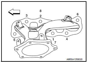
: Engine front
NOTE: Number 7 and 8 are not applicable to removal.
- Remove the exhaust manifold (LH) and gasket.
INSPECTION AFTER REMOVAL
Surface Distortion
- Use a suitable tool to check the flatness of the exhaust manifold mating surfaces as shown.
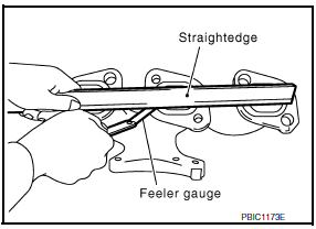
Limit : 0.3 mm (0.012 in)
- Replace the exhaust manifold if the measurement exceeds specifications.
INSTALLATION
Installation is in the reverse order of removal.
- Install the studs in the exhaust manifold (if removed), and tighten to specification.
Exhaust manifold studs : 15.4 N*m (1.6 kg-m, 11 ft-lb)
- Install the exhaust manifold gasket in the direction shown.
CAUTION: Do not reuse exhaust manifold gaskets.
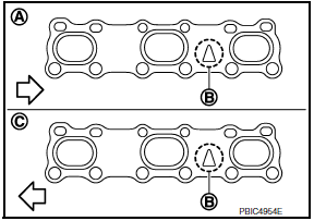
(A) : Bank 1
(B) : Triangle press
(C) : Bank 2
 : Engine front
- Install the exhaust manifold (LH) nuts and tighten to specification in the order shown.
 : Engine front
NOTE: Number 7 and 8 are tightened a second time.
CAUTION:
- Before installing a heated oxygen sensor 2 or air fuel ratio (A/F) sensor 1, clean the exhaust manifold threads using the oxygen sensor thread cleaner tool and apply anti-seize lubricant.
Oxygen sensor thread cleaner : (J-43897-18)
Oxygen sensor thread cleaner
: (J-43897-12)
- Do not over-tighten the air fuel ratio (A/F) sensor 1 or heated oxygen sensors 2. Doing so may cause damage.
Tool numbers : KV10114400 (J-38365)
: KV991J0050 (J-44626)
Removal and Installation (RH)
REMOVAL
WARNING:
- Perform the work when the exhaust and cooling system have completely cooled down.
- When removing the front and rear engine mounting through bolts and nuts, lift the engine up slightly for safety. For engine slingers, refer to EM-103, "Removal and Installation".
- Remove the engine and transaxle assembly. Refer to EM-103, "Removal and Installation".
- Remove the (RH) three way catalyst supports.
- Remove rear engine mount bracket. Refer to EM-103, "Removal and Installation".
- Remove heated oxygen sensor 2 (bank 1), air fuel ratio (A/F) sensor 1 (bank 1).
- Remove harness connector from heated oxygen sensor 2 (bank 1) and air fuel ratio (A/F) sensor 1, and disconnect the harness from the bracket and middle clamp.
- Remove both heated oxygen sensors 2 (bank 1) and air fuel ratio (A/F) sensors 1 using Tool.
Tool numbers : KV10114400 (J-38365)
: KV991J0050 (J-44626)
CAUTION:
- Be careful not to damage heated oxygen sensors 2 or air fuel ratio (A/F) sensors 1
- Discard any heated oxygen sensor 2 which has been dropped from a height of more than 0.5 m (19.7 in) onto a hard surface such as a concrete floor; replace with a new sensor.
- Remove exhaust manifold heat shield (RH) and three way catalyst heat shields (RH) using power tool.
- Remove the three way catalyst (bank 1) by loosening the bolts first and then removing the nuts and through bolts.
- Loosen the exhaust manifold nuts in the reverse order as shown and remove the exhaust manifold (RH).
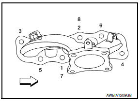
 : Engine front
NOTE: Number 7 and 8 are not applicable to removal.
INSPECTION AFTER REMOVAL
Surface Distortion
- Use a suitable tool to check the flatness of the exhaust manifold mating surfaces as shown.
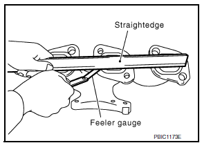
Limit : 0.3mm (0.012 in)
INSTALLATION
Installation is in the reverse order of removal.
CAUTION: Do not reuse exhaust manifold gaskets.
- Install the exhaust manifold nuts in the order as shown (A).
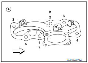
 :Engine front
NOTE: Number 7 and 8 are tightened a second time.
CAUTION:
- Before installing a heated oxygen sensor 2 or air fuel ratio (A/F) sensor 1, clean the exhaust manifold threads using the oxygen sensor thread cleaner tool, and apply anti-seize lubricant.
Tool numbers : J-43897-18
: J-43897-12
- Do not over-tighten the air fuel ratio (A/F) sensor 1 or heated oxygen sensors 2. Doing so may cause damage.
Tool numbers : KV10114400 (J-38365)
: KV991J0050 (J-44626)
 Intake Manifold
Removal and Installation
Intake manifold
Intake manifold gaskets
Refer to INSTALLATION
REMOVAL
WARNING: To avoid the danger of being
scalded, do not drain the coolant when th ...
 Oil Pan And Oil Strainer
Exploded View
Oil pan baffle
O-ring
Gasket
Oil pressure switch
Oil cooler gasket
Oil cooler
Oil cooler connection
Oil filter
Lower oil pan
Oil strainer
Rear plate cove ...
Other materials:
Removal and installation
WHEEL HUB
Removal and Installation
Knuckle
Baffle plate
Wheel hub assembly
Brake rotor
Wheel nut
Anchor block
Wheel sensor
Parking brake cable
Refer to PB-6, "Exploded View".
Refer to BRC-103, "Removal and Installation
- Rear Wheel Sensor".
&nb ...
System maintenance
The two radar sensors 1 for the BSW and
RCTA systems are located near the rear bumper.
Always keep the area near the radar sensors
clean.
The radar sensors may be blocked by temporary
ambient conditions such as splashing water, mist
or fog.
The blocked condition may also be caused b ...
Daytime running light system
Wiring Diagram
...
Nissan Maxima Owners Manual
- Illustrated table of contents
- Safety-Seats, seat belts and supplemental restraint system
- Instruments and controls
- Pre-driving checks and adjustments
- Monitor, climate, audio, phone and voice recognition systems
- Starting and driving
- In case of emergency
- Appearance and care
- Do-it-yourself
- Maintenance and schedules
- Technical and consumer information
Nissan Maxima Service and Repair Manual

0.006