Nissan Maxima Service and Repair Manual: Horn function
Description
Perform answer-back for each operation with horn.
Component Function Check
1. CHECK FUNCTION
- Select HORN in "ACTIVE TEST" mode with CONSULT.
- Check the horn (high/low) operation.

Diagnosis Procedure
1. CHECK HORN FUNCTION
Check horn function with horn switch
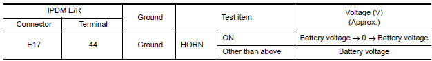
2. CHECK HORN RELAY POWER SUPPLY
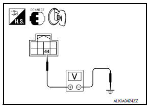
- Turn ignition switch ON.
- Perform "ACTIVE TEST" ("HORN") with CONSULT.
- Using an oscilloscope or analog voltmeter, check voltage between IPDM E/R connector and ground.
3. CHECK INTERMITTENT INCIDENT
 Key slot illumination
Description
Blinks when Intelligent Key insertion is required.
Component Function Check
1. CHECK FUNCTION
With CONSULT
Check key slot illumination KEY SLOT ILLUMI in Active Test mode.
Diagnosi ...
 Combination meter display function
Description
Displays each operation method guide and warning for system malfunction.
Component Function Check
1. CHECK FUNCTION
With CONSULT
Check the operation with ("LCD") in the Active Test. ...
Other materials:
Illumination
Removal and Installation
TRUNK ROOM LAMP
Removal
Release the tab (A), then swing open the lens.
: Front
Remove the bulb (3).
Release the tab (B), then pull trunk room lamp (2) away from
body opening.
Disconnect the connector (1) and remove trunk room lamp
Installation
Install ...
Front wiper does not operate
Description
The front wiper does not operate under any operation conditions
Diagnosis Procedure
1. CHECK WIPER RELAY OPERATION
IPDM E/R AUTO ACTIVE TEST
Start IPDM E/R auto active test. Refer to PCS-11, "Diagnosis
Description".
Check that the front wiper operates at the LO/HI operation. ...
Sunroof does not operate properly
Diagnosis Procedure
1.CHECK SUNROOF MECHANISM
Check the following.
Operation malfunction caused by sunroof mechanism deformation,
pinched harness or other foreign materials
Operation malfunction and interference with other parts by poor
installation
2.CHECK SUNROOF MOTOR ASSEMBLY PO ...
Nissan Maxima Owners Manual
- Illustrated table of contents
- Safety-Seats, seat belts and supplemental restraint system
- Instruments and controls
- Pre-driving checks and adjustments
- Monitor, climate, audio, phone and voice recognition systems
- Starting and driving
- In case of emergency
- Appearance and care
- Do-it-yourself
- Maintenance and schedules
- Technical and consumer information
Nissan Maxima Service and Repair Manual

0.0081