Nissan Maxima Service and Repair Manual: Key slot illumination
Description
Blinks when Intelligent Key insertion is required.
Component Function Check
1. CHECK FUNCTION
With CONSULT
Check key slot illumination KEY SLOT ILLUMI in Active Test mode.
Diagnosis Procedure
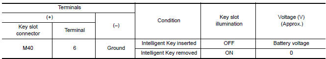
1. CHECK KEY SLOT ILLUMINATION OUTPUT SIGNAL
Check voltage between key slot connector and ground.
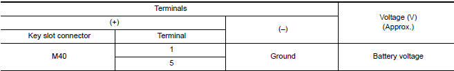
2. CHECK KEY SLOT POWER SUPPLY CIRCUIT
- Turn ignition switch OFF.
- Disconnect key slot connector.
- Check voltage between slot connector and ground.
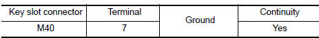
3. CHECK KEY SLOT GROUND CIRCUIT
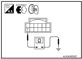
Check continuity between key slot connector and ground.
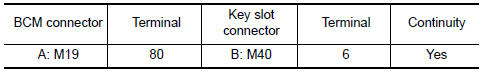
4. CHECK KEY SLOT CIRCUIT
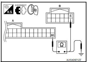
- Disconnect BCM and key slot connector.
- Check continuity between BCM connector and key slot connector.
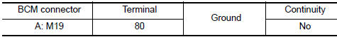
- Check continuity between BCM connector and ground.
5. CHECK KEY SLOT
6. CHECK INTERMITTENT INCIDENT
 Intelligent key
Description
The following functions are available when having and carrying the
Intelligent Key.
Door lock/unlock
Trunk open
Remote control entry function and panic alarm function are avai ...
 Horn function
Description
Perform answer-back for each operation with horn.
Component Function Check
1. CHECK FUNCTION
Select HORN in "ACTIVE TEST" mode with CONSULT.
Check the horn (high/low) operation. ...
Other materials:
P0778 pressure control solenoid B
Description
The secondary pressure solenoid valve regulates the oil pump discharge
pressure to suit the driving condition
in response to a signal sent from the TCM.
DTC Logic
DTC DETECTION LOGIC
DTC CONFIRMATION PROCEDURE
CAUTION:
Always drive vehicle at a safe speed.
NOTE:
Immediate ...
Cleaning
If your windshield is not clear after using the
windshield-washer or if a wiper blade chatters
when running, wax or other material may be on
the blade or windshield.
Clean the outside of the windshield with a washer
solution or a mild detergent. Your windshield is
clean if beads do not form ...
ECU diagnosis information
TCM
Reference Value
VALUES ON THE DIAGNOSIS TOOL
TERMINAL LAYOUT
PHYSICAL VALUES
Fail-safe
The TCM has an electrical fail-safe mode. In this mode
TCM operates even if there is an error in a main electronic
control input/output signal circuit.
FAIL-SAFE FUNCTION
If any malf ...
Nissan Maxima Owners Manual
- Illustrated table of contents
- Safety-Seats, seat belts and supplemental restraint system
- Instruments and controls
- Pre-driving checks and adjustments
- Monitor, climate, audio, phone and voice recognition systems
- Starting and driving
- In case of emergency
- Appearance and care
- Do-it-yourself
- Maintenance and schedules
- Technical and consumer information
Nissan Maxima Service and Repair Manual

0.0055