Nissan Maxima Service and Repair Manual: Oil Pan And Oil Strainer
Exploded View
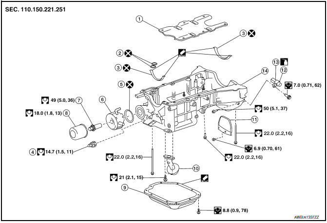
- Oil pan baffle
- O-ring
- Gasket
- Oil pressure switch
- Oil cooler gasket
- Oil cooler
- Oil cooler connection
- Oil filter
- Lower oil pan
- Oil strainer
- Rear plate cover
- Crankshaft position sensor (POS)
- O-ring
- Upper oil pan
Removal and Installation (Lower Oil Pan)
REMOVAL
WARNING: Do not remove the oil pan until the exhaust system and cooling system are completely cooled.
- Drain the engine oil. Refer to LU-9, "Changing Engine Oil".
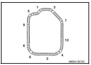
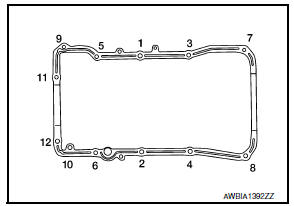
- Loosen the lower oil pan bolts in the reverse order as shown using power tool.
- Remove the lower oil pan.
- Insert Tool between the lower oil pan and the upper oil pan.
Tool number : KV10111100 (J-37228)
CAUTION:
- Be careful not to damage the mating surface.
- Do not insert a screwdriver, this will damage the mating surfaces.
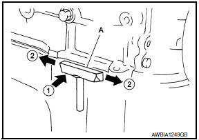
- In areas where the cutter is difficult to use, use a plastic hammer to lightly tap (1) the cutter where the liquid gasket is applied. Use a plastic hammer to slide (2) the cutter by tapping on the side.
- If re-installing the original lower oil pan, remove the old sealant from the mating surfaces using suitable tool.
- Also remove the old sealant from mating surface of the upper oil pan.
- Remove the old sealant from the bolt holes and threads.
CAUTION: Do not scratch or damage the mating surfaces when cleaning off the old sealant.
INSPECTION AFTER REMOVAL
Clean debris from the oil strainer.
INSTALLATION
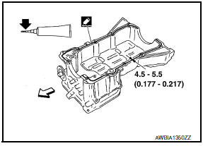
- Apply a continuous bead of sealant to the lower oil pan.
- Use Genuine Silicone RTV Sealant, or equivalent. Refer to GI- 21, "Recommended Chemical Products and Sealants".
- Be sure the sealant is 4.5 - 5.5 mm (0.177 - 0.217 in) wide.
- Installation must be done within 5 minutes after applying sealant.
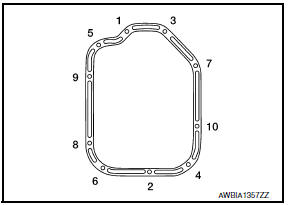
- Install the lower oil pan. Tighten the lower oil pan bolts in order as shown.
- Wait at least 30 minutes before refilling the engine with o
INSPECTION AFTER INSTALLATION
- Start the engine and check for leaks. Refer to LU-8, "Inspection".
- Inspect the engine oil level. Adjust as necessary. Refer to LU-8, "Inspection".
Removal and Installation (Upper Oil Pan)
REMOVAL
WARNING:
- Do not remove the oil pan until the exhaust system and cooling system are completely cooled.
- When removing the front and rear engine through bolts and
nuts, lift the engine up slightly for safety.
For engine slingers, refer to EM-103, "Removal and Installation".
CAUTION: When removing the upper oil pan from the engine, first remove the crankshaft position sensor (POS).
Be careful not to damage sensor edges or signal plate teeth.
NOTE: When removing components such as hoses, tubes/lines, etc., cap or plug openings to prevent fluid from spilling.
- Remove the engine from the vehicle. Refer to EM-103, "Removal and Installation".
- Drain the engine oil. Refer to LU-9, "Changing Engine Oil".
- Remove the oil dipstick.
- Remove the drive belt. Refer to EM-14, "Removal and Installation".
- Disconnect the A/C compressor harness connector.
- Remove the A/C compressor bolts and remove the A/C compressor. Refer to HA-37, "Removal and Installation for Compressor".
- Remove coolant pipe bolts.
- Disconnect the coolant lines from the engine oil cooler.
- Remove the oil filter and engine oil cooler from the upper oil pan.
- Remove the oil pressure switch, and the crankshaft position sensor (POS) from the upper oil pan.
- Remove the lower oil pan. Refer to EM-36, "Removal and Installation (Lower Oil Pan)".
- Remove the upper oil pan.
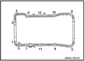
- Loosen the bolts in the order as shown, using power tool.
- Insert suitable tool into the notch (1) of the upper oil pan as shown.
- Pry off the upper oil pan by moving suitable tool up and down (2) as shown.
- Remove the O-ring seals from the bottom of the cylinder block and oil pump housing. Use new O-rings for installation.
CAUTION: Do not reuse O-rings.
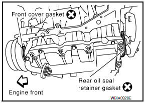
- Remove front cover gasket and rear oil seal retainer gasket.
- Remove the oil strainer.
- If re-installing the original oil pan, remove the old sealant from the mating surfaces using suitable tool.
- Also remove the old sealant from mating surface of the cylinder block.
- Remove the old sealant from the bolt holes and threads.
CAUTION: Do not scratch or damage the mating surfaces when cleaning off the old sealant.
INSPECTION AFTER REMOVAL
Clean debris from oil strainer.
INSTALLATION
- Install oil strainer and tighten bolt to specified torque. Refer to EM-37, "Removal and Installation (Upper Oil Pan)".
- Apply Genuine Silicone RTV Sealant or equivalent, to the front
cover gasket and the rear oil seal retainer gasket as shown.
Refer to GI-21, "Recommended Chemical Products and Sealants".
CAUTION:
- Installation should be done within 5 minutes after applying liquid gasket.
- Do not fill the engine with oil for at least 30 minutes after the components are installed to allow the sealant to cure.
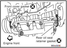
- Install the front cover gasket and rear oil seal retainer gasket as shown.
CAUTION: Do not reuse front cover gasket and rear oil seal retainer gasket
- Apply a bead of sealant to the cylinder block mating surface of the upper oil pan as shown.
- Use Genuine Silicone RTV Sealant, or equivalent. Refer to GI- 21, "Recommended Chemical Products and Sealants".
- Be sure the sealant is applied 4.5 - 5.5 mm (0.177 - 0.217 in) as shown.
 : Engine front
 : Cut here
CAUTION:
- Installation should be done within 5 minutes after applying liquid gasket.
- Do not fill the engine with oil for at least 30 minutes after the components are installed to allow the sealant to cure.
- Install new O-rings on the cylinder block and oil pump body.
CAUTION: Do not reuse O-rings.
- Install the upper oil pan and tighten the upper oil pan bolts in the order shown.
CAUTION:
- Installation should be done within 5 minutes after applying liquid gasket.
- Do not fill the engine with oil for at least 30 minutes after the components are installed to allow the sealant to cure.
- Install the lower oil pan. Refer to EM-36, "Removal and Installation (Lower Oil Pan)".
- Installation of the remaining components is in the reverse order of removal.
INSPECTION AFTER INSTALLATION
- Before starting engine, check oil/fluid levels including engine coolant and engine oil. If less than required quantity, fill to the specified level. Refer to MA-15, "FOR USA AND CANADA : Fluids and Lubricants" (United States and Canada) or MA-16, "FOR MEXICO : Fluids and Lubricants" (Mexico).
- Use procedure below to check for fuel leakage.
- Turn ignition switch ON (with engine stopped). With fuel pressure applied to fuel piping, check for fuel leakage at connection points.
- Start engine. With engine speed increased, check again for fuel leakage at connection points.
- Run engine to check for unusual noise and vibration.
NOTE: If hydraulic pressure inside timing chain tensioner drops after removal and installation, slack in the guide may generate a pounding noise during and just after engine start. However, this is normal. Noise will stop after hydraulic pressure rises.
- Warm up engine thoroughly to make sure there is no leakage of fuel, exhaust gas, or any oils/fluids including engine oil and engine coolant.
- Bleed air from passages in lines and hoses, such as in cooling system.
- After cooling down engine, again check oil/fluid levels including engine oil and engine coolant. Refill to specified level, if necessary.
- Summary of the inspection items:
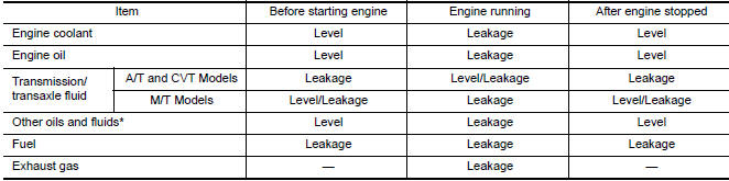
*Power steering fluid, brake fluid, etc.
 Exhaust Manifold And Three Way Catalyst
Exploded View
Gasket
Exhaust manifold (RH)
Exhaust manifold heat shield (RH)
Air fuel ratio sensor 1 (bank 1)
Ring gasket
Three way catalyst (bank 1)
Three way catalyst support ( ...
 Ignition Coil
Exploded View
Ignition coil
Spark plug
Rocker cover (RH)
Rocker cover (LH)
Removal and Installation (LH)
REMOVAL
Remove engine room cover. Refer to EM-23, "Removal and Installati ...
Other materials:
Power consumption control system
System Diagram
System Description
OUTLINE
BCM incorporates a power saving control function that reduces the
power consumption according to the
vehicle status.
BCM switches the status (control mode) by itself with the power
saving control function. It performs the sleep
reques ...
Wiring diagram
TIRE PRESSURE MONITORING SYSTEM
Wiring Diagram
...
Air mix door control system
System Diagram
System Description
The air mix doors are automatically controlled so that in-vehicle temperature
is maintained at a predetermined
value by the temperature setting, ambient temperature, intake temperature and
amount of sunload.
SYSTEM OPERATION
The A/C auto amp. receiv ...
Nissan Maxima Owners Manual
- Illustrated table of contents
- Safety-Seats, seat belts and supplemental restraint system
- Instruments and controls
- Pre-driving checks and adjustments
- Monitor, climate, audio, phone and voice recognition systems
- Starting and driving
- In case of emergency
- Appearance and care
- Do-it-yourself
- Maintenance and schedules
- Technical and consumer information
Nissan Maxima Service and Repair Manual

0.0066