Nissan Maxima Service and Repair Manual: RGB (R: red) signal circuit
Description
Transmit the image displayed with AV control unit with RGB signal to the display unit.
Diagnosis Procedure
1.CHECK CONTINUITY RGB (R: RED) SIGNAL CIRCUIT
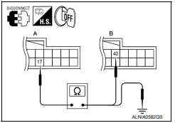
- Turn ignition switch OFF.
- Disconnect display unit connector M141 and AV control unit connector M117.
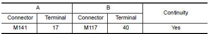
- Check continuity between display unit harness connector M141 (A) terminal 17 and AV control unit harness connector M117 (B) terminal 40.
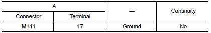
- Check continuity between display unit harness connector M141 (A) terminal 17 and ground.
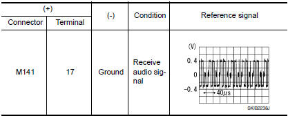
2.CHECK RGB (R: RED) SIGNAL
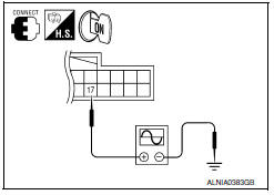
- Connect display unit connector M141 and AV control unit connector M117.
- Turn ignition switch ON.
- Check signal between display unit harness connector M141 terminal 17 and ground.
 Power supply and ground circuit
AV CONTROL UNIT
AV CONTROL UNIT : Diagnosis Procedure
1.CHECK FUSES
Check that the following fuses of the AV control unit are not blown.
2.POWER SUPPLY CIRCUIT CHECK
Disconnect AV contro ...
 RGB (G: green) signal circuit
Description
Transmit the image displayed with AV control unit with RGB signal to the
display unit.
Diagnosis Procedure
1.CHECK CONTINUITY RGB (G: GREEN) SIGNAL CIRCUIT
Turn ignition switc ...
Other materials:
Using the panic alarm
If you are near your vehicle and feel threatened,
you may activate the panic alarm to call attention
by pressing and holding the button
on the
Intelligent Key for longer than 1 second.
The panic alarm and headlights will stay on for a
period of time.
The panic alarm stops when:
It ...
Rear combination lamp
Disassembly and Assembly
Rear combination lamp
Rear side marker lamp socket
Rear side marker lamp bulb
Rear turn signal lamp socket
Rear turn signal lamp bulb
Back-up lamp socket
Back-up lamp bulb
DISASSEMBLY
Rotate the rear side marker lamp socket counterclockwise and ...
M&A branch line circuit
Diagnosis Procedure
1.CHECK CONNECTOR
Turn the ignition switch OFF.
Disconnect the battery cable from the negative terminal.
Check the terminals and connectors of the combination meter for
damage, bend and loose connection
(unit side and connector side).
2.CHECK HARNESS FOR OPEN CI ...
Nissan Maxima Owners Manual
- Illustrated table of contents
- Safety-Seats, seat belts and supplemental restraint system
- Instruments and controls
- Pre-driving checks and adjustments
- Monitor, climate, audio, phone and voice recognition systems
- Starting and driving
- In case of emergency
- Appearance and care
- Do-it-yourself
- Maintenance and schedules
- Technical and consumer information
Nissan Maxima Service and Repair Manual

0.0083