Nissan Maxima Service and Repair Manual: Chassis and body maintenance
IN-CABIN MICROFILTER
IN-CABIN MICROFILTER : Removal and Installation
REMOVAL
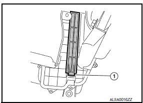
- Disengage the filter cover tab (1) by pushing up and pull out to remove the filter cover.
- Remove the in-cabin microfilter from the blower unit.
INSTALLATION
Installation is in the reverse order of removal.
EXHAUST SYSTEM
EXHAUST SYSTEM : Inspection
Check exhaust pipes, muffler and mounting for improper attachment, leaks, cracks, damage, chafing or deterioration.
- If anything is found, repair or replace damaged parts.
CVT FLUID
CVT FLUID : Inspection
CHECKING CVT FLUID
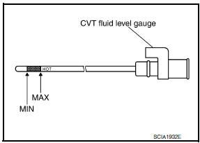
The fluid level should be checked with the fluid warmed up to 50 to 80C (122 to 176F). The fluid level check procedure is as follows:
- Check for fluid leakage.
- With the engine warmed up, drive the vehicle in an urban area.
When ambient temperature is 20C (68F), it takes about 10 minutes for the CVT fluid to warm up to 50 to 80C (122 to 176F).
- Park the vehicle on a level surface.
- Apply parking brake firmly.
- With engine at idle, while depressing brake pedal, move shift selector throughout the entire shift range.
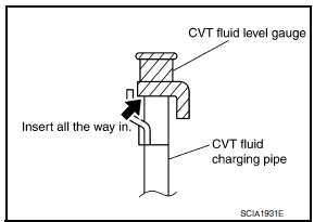
- Pull out the CVT fluid level gauge from the CVT fluid charging pipe after pressing the tab on the CVT fluid level gauge to release the lock.
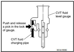
- Wipe fluid off the CVT fluid level gauge. Insert the CVT fluid level gauge rotating 180 from the originally installed position, then securely push the CVT fluid level gauge until it meets the top end of the CVT fluid charging pipe.
CAUTION: When wiping away the CVT fluid level gauge, always use lint-free paper, not a cloth rag.
- Place the shift selector in "P" or "N" position and check that the fluid level is within the specified range.
CAUTION: When reinstalling CVT fluid level gauge, insert it into the CVT fluid charging pipe and rotate it to the original installation position until securely locked.
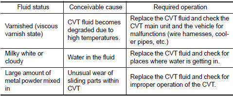
CVT FLUID CONDITION
Check CVT fluid condition.
- If CVT fluid is very dark or smells burned, check operation of CVT.
Flush cooling system after repair of CVT.
- If CVT fluid contains frictional material (clutches, brakes, etc.), inspect and clean the CVT fluid cooler mounted in the radiator and flush cooler line using cleaning solvent and compressed air after repair of CVT. Refer to TM-157, "Cleaning".
CVT FLUID : Changing
CAUTION: Replace a O-ring with new ones at the final stage of the operation when installing.
- Remove drain plug from oil pan.
- Remove O-ring from drain plug and discard the O-ring.
- Install a new O-ring on drain plug.
CAUTION: Do not reuse O-ring.
- Install drain plug in oil pan. Refer to TM-177, "Exploded View".
- Fill CVT fluid from CVT fluid charging pipe to the specified level.
CAUTION:
- Use only Genuine NISSAN CVT Fluid NS-2. Do not mix with other fluid.
- Using CVT fluid other than Genuine NISSAN CVT Fluid NS-2 will deteriorate in driveability and CVT durability, and may damage the CVT, which is not covered by the warranty.
- When filling CVT fluid, take care not to scatter heat generating parts such as exhaust.
- Sufficiently shake the container of CVT fluid before using.
- Delete CVT fluid deterioration date with CONSULT after changing CVT fluid. Refer to TM-38, "CONSULT Function".
- With the engine warmed up, drive the vehicle in an urban area.
NOTE: When ambient temperature is 20C (68F), it takes about 10 minutes for the CVT fluid to warm up to 50 to 80C (122 to 176F).
- Check CVT fluid level and condition.
- Repeat steps 1 to 5 if CVT fluid has been contaminated.
WHEELS
WHEELS : Inspection
ALUMINUM WHEEL
- Check tires for wear and improper inflation.
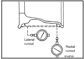
- Check wheels for deformation, cracks and other damage. If deformed, remove wheel and check wheel runout.
- Remove tire from aluminum wheel and then mount the wheel on a tire balancer machine. Remove the transmitter, refer to WT-59, "Removal and Installation".
- Set dial indicator as shown and rotate the wheel to check for runout.
- Replace wheel if runout exceeds specification.
WHEELS : Adjustment
BALANCING WHEELS (ADHESIVE WEIGHT TYPE)
Preparation Before Adjustment
Remove inner and outer balance weights from the road wheel using releasing agent, remove double-faced adhesive tape from the road wheel.
CAUTION:
- Be careful not to scratch the road wheel during removal.
- After removing double-faced adhesive tape, wipe clean all traces of releasing agent from the road wheel.
Wheel Balance Adjustment
- If a balancer machine has an adhesive weight mode setting, select
the adhesive weight mode setting and
skip Step 2. below. If a balancer machine only has the clip-on (rim flange)
weight mode setting, follow Step 2.
to calculate the correct size adhesive weight.
- Set road wheel on balancer machine using the center hole as a guide. Start the balancer machine.
- For balancer machines that only have a clip-on (rim flange) weight mode setting, follow this step to calculate the correct size adhesive weight to use. When inner and outer imbalance values are shown on the balancer machine indicator, multiply outer imbalance value by 5/3 (1.67) to determine balance weight that should be used. Select the outer balance weight with a value closest to the calculated value above and install in to the designated outer position of, or at the designated angle in relation to the road wheel.
- Indicated imbalance value × 5/3 = balance weight to be installed
Calculation example: 23 g (0.81 oz) × 5/3 (1.67) = 38.33 g (1.35 oz) ⇒ 40 g (1.41 oz) balance weight (closer to calculated balance weight value) NOTE: Note that balance weight value must be closer to the calculated balance weight value.
Example:
37.4 ⇒ 35 g (1.23 oz)
37.5 ⇒ 40 g (1.41 oz)
- Install balance weight in the position shown.
CAUTION:
- Do not install the inner balance weight before installing the outer balance weight.
- Before installing the balance weight, be sure to clean the mating surface of the road wheel.
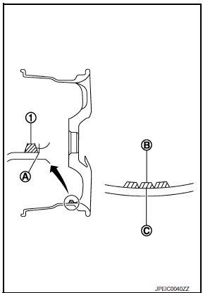
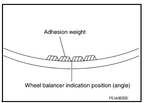
- When installing balance weight (1) to road wheel, set it into the grooved area (A) on the inner wall of the road wheel as shown so that the balance weight center (B) is aligned with the balancer machine indication position (angle) (C).
CAUTION:
- Always use Genuine NISSAN adhesive balance weights.
- Balance weights are non-reusable; always replace with new ones.
- Do not install more than three sheets of balance weight.
- If calculated balance weight value exceeds 50 g (1.76 oz), install two balance weight sheets in line with each other as shown. CAUTION: Do not install one balance weight sheet on top another.
- Start balancer machine again.
- Install balance weight on inner side of road wheel in the balancer machine indication position (angle). CAUTION: Do not install more than two balance weights.
- Start balancer machine. Make sure that inner and outer residual imbalance values are 5 g (0.17 oz) each or below.
- If either residual imbalance value exceeds 5 g (0.17 oz), repeat installation procedures.
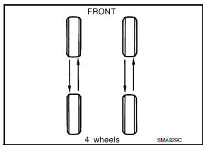
TIRE ROTATION

- Use power tool to remove wheel and tire assembly.
- Follow the maintenance schedule for tire rotation service
intervals.
Refer to MA-5, "FOR USA AND CANADA : Explanation of General Maintenance" (United States and Canada) or MA-7, "FOR MEXICO : Explanation of General Maintenance" (Mexico).
CAUTION:
- Do not include the T-type spare tire when rotating the tires.
- When installing wheels, tighten them diagonally by dividing the work two to three times in order to prevent the wheels from developing any distortion.
- Be careful not to tighten wheel nut at torque exceeding the criteria for preventing strain of disc rotor.
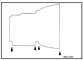
BRAKE FLUID LEVEL AND LEAKS
BRAKE FLUID LEVEL AND LEAKS : Inspection
LEVEL CHECK
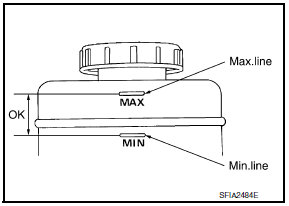
- Make sure that a brake fluid level in reservoir tank is between MAX and MIN lines as shown.
- Visually check around reservoir tank for fluid leakage.
- If the level is excessively low, check brake system for leaks.
- If brake warning lamp remains illuminated after parking brake pedal is released, check brake system for fluid leaks.
BRAKE LINES AND CABLES
BRAKE LINES AND CABLES : Inspection
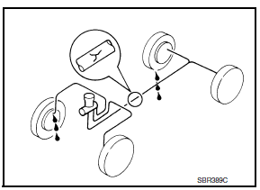
- Check brake fluid lines and parking brake cables for improper attachment, leaks, chafing, abrasions, deterioration, etc.
BRAKE FLUID
BRAKE FLUID : Drain and Refill
CAUTION:
- Refill with new brake fluid. Refer to MA-15, "FOR USA AND CANADA : Fluids and Lubricants" (for United States and Canada) or MA-16, "FOR MEXICO : Fluids and Lubricants" (for Mexico).
- Do not reuse drained brake fluid.
- Do not let brake fluid splash on the painted surfaces of the body. This might damage the paint. If brake fluid is splashed on painted areas, wash it away with water immediately.
- Before working, disconnect ABS actuator and electric unit (control unit) connector or battery negative terminal.
- Turn ignition switch OFF and disconnect ABS actuator and electric unit (control unit) connector or battery negative terminal.
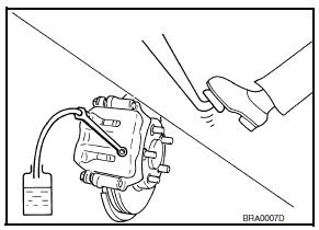
- Connect a vinyl tube to bleed valve.
- Depress brake pedal, loosen bleed valve, and gradually remove brake fluid.
- Make sure there is no foreign material in the reservoir tank, and refill with new brake fluid.
- Rest foot on brake pedal. Loosen bleed valve. Slowly depress
brake pedal until it stops. Tighten bleed valve. Release brake
pedal. Repeat the process a few times, then pause to add new
brake fluid to master cylinder. Continue until the new brake fluid
flows out of bleed valve.
Bleed the air out of the brake hydraulic system. Refer to BR-16, "Bleeding Brake System".
FRONT BRAKE
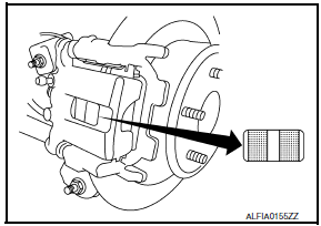
FRONT BRAKE : Inspection of Pad
PAD WEAR
- Check pad thickness from the inspection hole on cylinder body.
Check using a scale if necessary.
Standard thickness : Refer to BR-46, "Front Disc
Brake".
Minimum thickness : Refer to BR-46, "Front Disc
Brake".
FRONT BRAKE : Inspection of Rotor
VISUAL
Check surface of disc rotor for uneven wear, cracks, and serious damage. Replace as necessary.
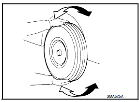
RUNOUT
- Attach disc rotor to wheel hub using wheel nuts (at two or more positions).
- Inspect runout using a dial gauge placed at 10 mm (0.39 in) inside the disc edge.
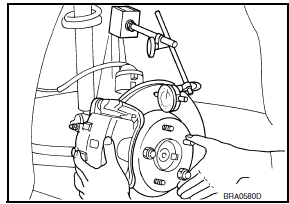
Runout limit : Refer to BR-46, "Front Disc Brake".
(with it attached to the vehicle)
NOTE: Before measuring, make sure that wheel bearing axial end play is within the specification. Refer to FAX-5, "Inspection".
- When runout exceeds limit value, displace mounting positions of disc rotor by one hole. Then find a position of the minimum value for runout.
- If runout is outside the specified value after performing the above operation, refinish disc rotor.
THICKNESS
Check thickness of the disc rotor using a micrometer. Replace disc rotor if thickness is under the wear limit.
Standard thickness : Refer to BR-46, "Front
Disc Brake".
Minimum thickness : Refer to BR-46, "Front
Disc Brake".
Thickness variation
(Measured at 8 positions)
: Refer to BR-46, "Front
Disc Brake".
REAR BRAKE
REAR BRAKE : Inspection of Pad
PAD WEAR
- Check pad thickness from the inspection hole on cylinder body.
Check using a scale if necessary.
Standard thickness : Refer to BR-46, "Rear Disc
Brake".
Minimum thickness : Refer to BR-46, "Rear Disc
Brake".
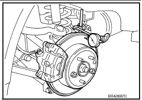
REAR BRAKE : Inspection of Rotor
VISUAL
Check surface of disc rotor for uneven wear, cracks, and serious damage. Replace if necessary
RUNOUT
- Attach disc rotor to wheel hub using wheel nuts (at two or more positions).
- Inspect runout using dial gauge placed at 10 mm (0.39 in) inside disc edge.
Runout limit : Refer to BR-46, "Rear Disc Brake".
(With it attached to the vehicle)
NOTE: Before measuring, make sure that wheel bearing axial end play is within the specification. Refer to RAX-5, "Inspection".
- When runout exceeds limit value, displace mounting positions of disc rotor by one hole. Then find a position of the minimum value for runout.
- If runout is outside the specified value after performing the above operation, refinish the disc rotor.
THICKNESS
Check the thickness of the disc rotor using a micrometer. Replace disc rotor if the thickness is less than the wear limit.
Standard thickness : Refer to BR-46, "Rear
Disc Brake".
Minimum thickness : Refer to BR-46, "Rear
Disc Brake".
Thickness variation
(Measured at 8 positions)
: Refer to BR-46, "Rear
Disc Brake".
STEERING GEAR AND LINKAGE
STEERING GEAR AND LINKAGE : Inspection
STEERING GEAR
- Check gear housing and boots for looseness, damage and grease leakage.
- Check connection with steering column for looseness.
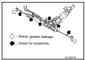
STEERING LINKAGE
Check ball joint, dust cover and other component parts for looseness, wear, damage and grease leakage.
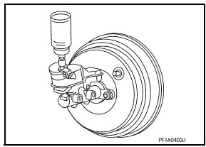
POWER STEERING FLUID AND LINES
POWER STEERING FLUID AND LINES : Inspection
FLUID LEVEL
- Check fluid level with engine stopped.
- Make sure that fluid level is between MIN and MAX.
- Fluid levels at HOT (A) and COLD (B) are different. Do not confuse them.
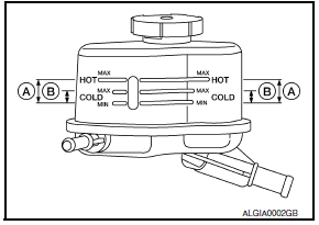
HOT (A) : Fluid temperature 50 - 80 C (122 - 176F)
COLD (B) : Fluid temperature 0 - 30C (32 - 86F)
CAUTION:
- The fluid level should not exceed the MAX line. Excessive fluid will cause fluid leakage from the cap.
- Do not reuse drained power steering fluid.
- Recommended fluid is Genuine Nissan PSF or equivalent.
FLUID LEAKAGE
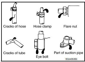
Check hydraulic connections for fluid leakage, cracks, damage, looseness, or wear.
- Run engine until the fluid temperature reaches 50 to 80 C (122 to 176F) in reservoir tank, and keep engine speed idle.
- Turn steering wheel several times from full left stop to full right stop.
- Hold steering wheel at each lock position for five seconds and carefully, check for fluid leakage. CAUTION: Do not hold the steering wheel in a locked position for more than 10 seconds. (There is the possibility that oil pump may be damaged.)
- If fluid leakage at connections is noticed, then loosen flare nut and then retighten. Do not overtighten connector as this can damage O-ring, washer and connector.
- If fluid leakage from oil pump is noticed, check oil pump. Refer to ST-28, "Removal and Installation".
- Check steering gear boots for accumulation of fluid indicating leakage from steering gear.
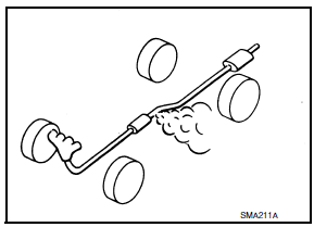
AXLE AND SUSPENSION PARTS
AXLE AND SUSPENSION PARTS : Inspection
Check front and rear axle and suspension parts for excessive play, cracks, wear or other damage.
- Shake each wheel to check for excessive play.
- Check wheel bearings for smooth operation.
- Check axle and suspension nuts and bolts for looseness.
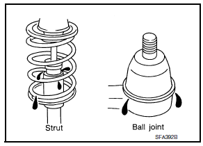
- Check strut (shock absorber) for oil leakage or other damage.
- Check suspension ball joint for grease leakage and ball joint dust cover for cracks or other damage.
DRIVE SHAFT
DRIVE SHAFT : Inspection
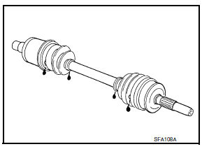
Check boot and drive shaft for cracks, wear, damage and grease leakage.
LOCKS, HINGES AND HOOD LATCH
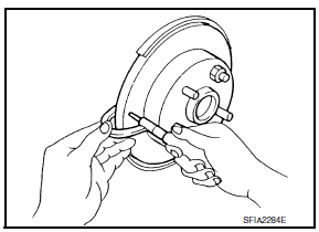
LOCKS, HINGES AND HOOD LATCH : Lubricating
SEAT BELT, BUCKLES, RETRACTORS, ANCHORS AND ADJUSTERS
SEAT BELT, BUCKLES, RETRACTORS, ANCHORS AND ADJUSTERS : Inspection
For details, refer to SB-3, "Inspection" in SB section.
- Check anchors for loose mounting
- Check belts for damage
- Check retractor for smooth operation
- Check function of buckles and tongues when buckled and released
CAUTION:
- After any collision, inspect all seat belt assemblies,
including retractors and other attached hardwares
(i.e., anchor bolt, guide rail set). Nissan recommends replacing all seat
belt assemblies in use
during a collision, unless not damaged and properly operating after minor
collision.
Also inspect seat belt assemblies not in use during a collision, and replace if damaged or improperly operating.
Seat belt pre-tensioner should be replaced even if the seat belts are not in use during a frontal collision where the driver and passenger air bags are deployed.
- If any component of seat belt assembly is questionable, do not repair, replace the entire seat belt assembly.
- If webbing is cut, frayed, or damaged, replace seat belt assembly.
- Do not oil tongue and buckle.
- Use a genuine NISSAN seat belt assembly.
 Engine maintenance (VQ35DE)
DRIVE BELTS
DRIVE BELTS : Checking Drive Belts
Idler pulley
Drive belt
Power steering oil pump
Drive belt auto-tensioner
Crankshaft pulley
Idler pulley
A/C compressor
Gener ...
Other materials:
Vehicle identification number (VIN) plate
The vehicle identification number (VIN) plate is
attached as shown. This number is the identification
for your vehicle and is used in the vehicle
registration.
Vehicle identification number (chassis number)
The vehicle identification number is located as
shown.
Engine serial number
...
Basic inspection
DIAGNOSIS AND REPAIR WORK FLOW
Work Flow
OVERALL SEQUENCE
DETAILED FLOW
1.GET INFORMATION FOR SYMPTOM
Get detailed information from the customer about the symptom (the condition
and the environment when the
incident/malfunction occurred).
2.CONFIRM THE SYMPTOM
Try to confirm the sympt ...
Automatic anti-glare rearview mirror
The inside mirror is designed so that it automatically
dims during night time conditions and according
to the intensity of the headlights of the
vehicle following you. The automatic anti-glare
feature is activated when the ignition switch is in
the ON position.
The indicator light will i ...
Nissan Maxima Owners Manual
- Illustrated table of contents
- Safety-Seats, seat belts and supplemental restraint system
- Instruments and controls
- Pre-driving checks and adjustments
- Monitor, climate, audio, phone and voice recognition systems
- Starting and driving
- In case of emergency
- Appearance and care
- Do-it-yourself
- Maintenance and schedules
- Technical and consumer information
Nissan Maxima Service and Repair Manual

0.0055