Nissan Maxima Service and Repair Manual: Fuel pressure
Inspection
FUEL PRESSURE RELEASE
With CONSULT
- Turn ignition switch ON.
- Perform "FUEL PRESSURE RELEASE" in "WORK SUPPORT" mode with CONSULT.
- Start engine.
- After engine stalls, crank it two or three times to release all fuel pressure.
- Turn ignition switch OFF.
Without CONSULT
- Remove fuel pump fuse located in IPDM E/R. Refer to FL-6, "Removal and Installation".
- Start engine.
- After engine stalls, crank it two or three times to release all fuel pressure.
- Turn ignition switch OFF.
- Reinstall fuel pump fuse after servicing fuel system.
FUEL PRESSURE CHECK
CAUTION: Before disconnecting fuel line, release fuel pressure from fuel line to eliminate danger.
NOTE:
- Prepare pans or saucers under the disconnected fuel line because the fuel may spill out. The fuel pressure cannot be completely released because A35 models do not have fuel return system.
- Be careful not to scratch or get the fuel hose connection area dirty when servicing, so that the quick connector o-ring maintains seal ability.
- Use Fuel Pressure Gauge Kit [SST (J-44321)] and Fuel Pressure Adapter [SST (J-44321-6)] to check fuel pressure.
- Release fuel pressure to zero.
- Remove fuel hose using Quick Connector Release [SST (J-45488)]. Refer to FL-10, "Exploded View".
- Do not twist or kink fuel hose because it is plastic hose.
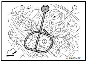
- Do not remove fuel hose (3) from quick connector.
- Keep fuel hose connections clean.
- Install Fuel Pressure Adapter [SST (J-44321-6)] (2) and Fuel Pressure Gauge kit [SST (J44321)] (1) as shown in figure.
- Do not distort or bend fuel rail tube when installing fuel pressure gauge adapter.
- When reconnecting fuel hose, check the original fuel hose for damage and abnormality.
- Turn ignition switch ON (reactivate fuel pump) and check for fuel leakage.
- Start engine and check for fuel leakage.
- Read the indication of fuel pressure gauge kit [SST (J-44321)].
- During fuel pressure check, check for fuel leakage from fuel connection every 3 minutes.
At idling : Approximately 350 kPa (3.57 kg/cm2, 51 psi)
- If result is unsatisfactory, go to next step.
- Check the following.
- Fuel hoses and fuel tubes for clogging
- Fuel filter for clogging
- Fuel pump
- Fuel pressure regulator for clogging
- If OK, replace fuel pressure regulator.
If NG, repair or replace malfunctioning part.
- Before disconnecting Fuel Pressure Gauge kit [SST (J-44321)] and Fuel Pressure Adapter [SST (J- 44321-6)], release fuel pressure to zero.

 Evap leak check
Inspection
CAUTION:
Never use compressed air or a high pressure pump.
Never exceed 4.12 kPa (0.042 kg/cm2, 0.6 psi) of pressure in
EVAP system.
NOTE:
Do not start en ...
Other materials:
Hazard function
Symptom Table
HAZARD AND BUZZER REMINDER FUNCTION MALFUNCTION
NOTE:
Before performing the diagnosis in the following table, check
"Work flow". Refer to DLK-9, "Work Flow".
If the following symptoms are detected, check systems shown in
the "Diagnosis/service procedure" column ...
Inspection and adjustment
ADDITIONAL SERVICE WHEN REMOVING BATTERY NEGATIVE TERMINAL
ADDITIONAL SERVICE WHEN REMOVING BATTERY NEGATIVE TERMINAL : Description
Initial setting is necessary when battery terminal is removed.
CAUTION:
The following specified operations are not performed under the
non-initialized condition. ...
Manual shift mode
The transmission enters the manual shift mode by
moving the shift lever to the left side in the "D"
range. You can select the manual shift range
either by moving the shift lever up or down, or by
pulling the right-side or left-side paddle shifter (if
so equipped). To cancel the manual shift ...
Nissan Maxima Owners Manual
- Illustrated table of contents
- Safety-Seats, seat belts and supplemental restraint system
- Instruments and controls
- Pre-driving checks and adjustments
- Monitor, climate, audio, phone and voice recognition systems
- Starting and driving
- In case of emergency
- Appearance and care
- Do-it-yourself
- Maintenance and schedules
- Technical and consumer information
Nissan Maxima Service and Repair Manual

0.0055