
Nissan Maxima Service and Repair Manual: Evap leak check
Inspection
CAUTION:
- Never use compressed air or a high pressure pump.
- Never exceed 4.12 kPa (0.042 kg/cm2, 0.6 psi) of pressure in EVAP system.
NOTE:
- Do not start engine.
- Improper installation of EVAP service port adapter (commercial service tool) to the EVAP service port may cause a leakage.
WITH CONSULT
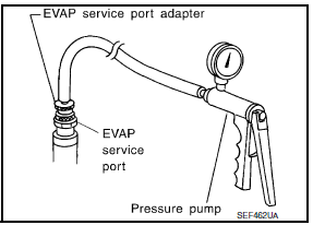
- To locate the EVAP leakage, install EVAP service port adapter (commercial service tool) and pressure pump to EVAP service port.
- Turn ignition switch ON.
- Select the "EVAP SYSTEM CLOSE" of "WORK SUPPORT MODE" with CONSULT.
- Touch "START". A bar graph (Pressure indicating display) will appear on the screen.
- Apply positive pressure to the EVAP system until the pressure indicator reaches the middle of the bar graph.
- Remove EVAP service port adapter (commercial service tool) and hose with pressure pump.
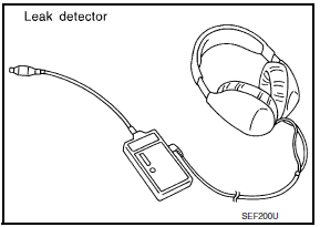
- Locate the leakage using a leakage detector (commercial service tool). Refer to EC-94, "System Diagram".
WITHOUT CONSULT
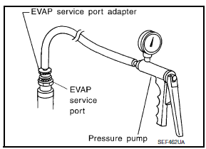
- To locate the EVAP leakage, install EVAP service port adapter (commercial service tool) and pressure pump to EVAP service port.
- Apply battery voltage between the terminals of EVAP canister vent control valve to make a closed EVAP system.
- To locate the leakage, deliver positive pressure to the EVAP system until pressure gauge points reach 1.38 to 2.76 kPa (0.014 to 0.028 kg/cm2, 0.2 to 0.4 psi).
- Remove EVAP service port adapter (commercial service tool) and hose with pressure pump.
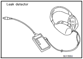
- Locate the leakage using a leakage detector (commercial service tool).
 Fuel pressure
Inspection
FUEL PRESSURE RELEASE
With CONSULT
Turn ignition switch ON.
Perform "FUEL PRESSURE RELEASE" in "WORK SUPPORT" mode with
CONSULT.
Start engine.
After engine stalls, crank it t ...
 Service data and specifications (SDS)
Idle Speed
Ignition Timing
Calculated Load Value
Mass Air Flow Sensor
*: Engine is warmed up to normal operating temperature and running under no
load. ...
Other materials:
Inspection and adjustment
Preliminary Check
NOTE: The Signal Tech II Tool (J-50190) can be used
to perform the following functions. Refer to the Signal Tech II User Guide
for additional information.
Activate and display TPMS transmitter IDs
Display tire pressure reported by the TPMS transmitter
...
Wiring diagram
TIRE PRESSURE MONITORING SYSTEM
Wiring Diagram
...
Automatic anti-glare rearview mirror
The inside mirror is designed so that it automatically
dims during night time conditions and according
to the intensity of the headlights of the
vehicle following you. The automatic anti-glare
feature is activated when the ignition switch is in
the ON position.
The indicator light will i ...
Nissan Maxima Owners Manual
- Illustrated table of contents
- Safety-Seats, seat belts and supplemental restraint system
- Instruments and controls
- Pre-driving checks and adjustments
- Monitor, climate, audio, phone and voice recognition systems
- Starting and driving
- In case of emergency
- Appearance and care
- Do-it-yourself
- Maintenance and schedules
- Technical and consumer information
Nissan Maxima Service and Repair Manual

0.0078