Nissan Maxima Service and Repair Manual: Horn
Description
Horn (high/low) is located inside of front bumper and operates when theft warning system is in alarm phase.
Component Function Check
1.CHECK FUNCTION
-
Select HORN in "ACTIVE TEST" mode with CONSULT.
-
Check the horn (high/low) operation.

Diagnosis Procedure
Regarding Wiring Diagram information, refer to SEC-136, "Wiring Diagram".
1.CHECK HORN FUNCTION
Check horn function with horn switch
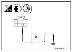
2.CHECK HORN RELAY POWER SUPPLY
-
Turn ignition switch ON.
-
Perform "ACTIVE TEST" ("HORN") with CONSULT.
-
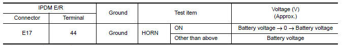
Using an analog voltmeter or an oscilloscope, check voltage between IPDM E/R harness connector E17 terminal 44 and ground.
3.CHECK HORN RELAY CIRCUIT
-
Turn ignition switch OFF.
-
Disconnect IPDM E/R and horn relay connector.
-
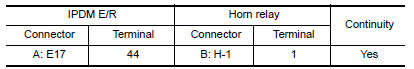
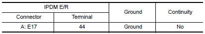
Check continuity between IPDM E/R harness connector E17 (A) terminal 44 and horn relay harness connector H1 (B) terminal 1.
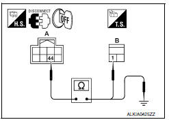
4. Check continuity between IPDM E/R harness connector E17 (A) terminal 44 and ground.
4.CHECK INTERMITTENT INCIDENT
Refer to GI-41, "Intermittent Incident".
 Key cylinder switch
Description
The main power window and door lock/unlock switch detects
condition of the door key cylinder switch and
transmits to BCM as the LOCK or UNLOCK signal.
Component Function Check
1.CHE ...
 Headlamp
Description
Headlamp lighting when theft warning system is in alarm
phase.
Component Function Check
1.CHECK HEADLAMP OPERATION
Check if headlamps operate by lighting switch.
Diagnosis Procedure ...
Other materials:
Removal and Installation
REMOVAL
Disconnect the battery negative terminal. Refer to PG-67, "Removal
and Installation (Battery)".
Disconnect the harness connector from the accelerator position
sensor.
Remove the three accelerator pedal nuts.
Remove the accelerator pedal and accelerator position sensor assembl ...
P1715 input speed sensor
Description
ECM receives input speed sensor signal from TCM via the CAN communication
line. ECM uses this signal for
engine control.
DTC Logic
DTC DETECTION LOGIC
NOTE:
If DTC P1715 is displayed with DTC UXXXX first perform the
trouble diagnosis for DTC UXXXX. Refer
to EC-161 ...
EVAP control system pressure sensor
Removal and Installation
REMOVAL
Remove rear stabilizer bar clamps and position rear stabilizer bar
aside. Refer to RSU-13, "Removal and Installation".
Disconnect EVAP hose from EVAP canister.
Disconnect EVAP control system pressure sensor.
Remove EVAP control s ...
Nissan Maxima Owners Manual
- Illustrated table of contents
- Safety-Seats, seat belts and supplemental restraint system
- Instruments and controls
- Pre-driving checks and adjustments
- Monitor, climate, audio, phone and voice recognition systems
- Starting and driving
- In case of emergency
- Appearance and care
- Do-it-yourself
- Maintenance and schedules
- Technical and consumer information
Nissan Maxima Service and Repair Manual

0.0063