Nissan Maxima Service and Repair Manual: Key cylinder switch
Description
The main power window and door lock/unlock switch detects condition of the door key cylinder switch and transmits to BCM as the LOCK or UNLOCK signal.
Component Function Check
1.CHECK DOOR KEY CYLINDER SWITCH INPUT SIGNAL
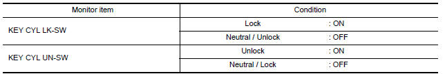
Check KEY CYL UN-SW, KEY CYL UN-SW in "DATA MONITOR" mode for "POWER DOOR LOCK SYSTEM" with CONSULT. Refer to BCS-19, "DOOR LOCK : CONSULT Function (BCM - DOOR LOCK)".
Diagnosis Procedure
Regarding Wiring Diagram information, refer to SEC-136, "Wiring Diagram".
1.CHECK DOOR KEY CYLINDER SWITCH INPUT SIGNAL
-
Turn ignition switch ON.
-
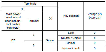
Check voltage between main power window and door lock/ unlock switch harness connector D7 terminal 4, 6 and ground.
2.CHECK DOOR KEY CYLINDER SIGNAL CIRCUIT
-
Turn ignition switch OFF.
-
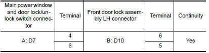
Disconnect main power window and door lock/unlock switch connector and front door lock assembly LH connector.
-
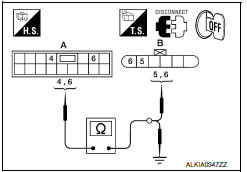
Check continuity between main power window and door lock/ unlock switch harness connector D7 (A) terminal 4, 6 and front door lock assembly LH harness connector D10 (B) 5, 6.
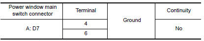
4. Check continuity between main power window and door lock/ unlock switch harness connector D7 (A) 4, 6 and ground.
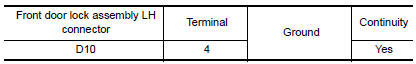
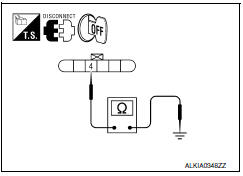
3.CHECK DOOR KEY CYLINDER SWITCH GROUND CIRCUIT
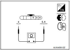
Check continuity between front door lock assembly LH harness connector D10 terminal 4 and ground.
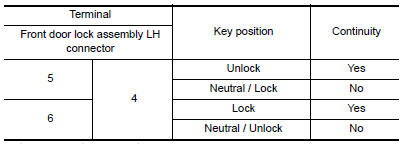
4.CHECK DOOR KEY CYLINDER SWITCH
Check door key cylinder switch.
Refer to SEC-86, "Component Inspection".
Component Inspection
COMPONENT INSPECTION
1.CHECK DOOR KEY CYLINDER SWITCH
Check front door lock assembly LH.
Special Repair Requirement
1. PERFORM INITIALIZATION PROCEDURE
Perform initialization procedure. Refer to PWC-7, "ADDITIONAL SERVICE WHEN REMOVING BATTERY NEGATIVE TERMINAL : Special Repair Requirement" and PWC-7, "ADDITIONAL SERVICE WHEN REPLACING CONTROL UNIT : Special Repair Requirement".
GO TO 2
2. CHECK ANTI-PINCH OPERATION
Check anti-pinch operation. Refer to PWC-7, "ADDITIONAL SERVICE WHEN REMOVING BATTERY NEGATIVE TERMINAL : Special Repair Requirement" and PWC-7, "ADDITIONAL SERVICE WHEN REPLACING CONTROL UNIT : Special Repair Requirement".
End.
 Key slot illumination
Description
Blinks when Intelligent Key insertion is required.
Component Function Check
1.CHECK FUNCTION
With CONSULT
Check key slot illumination ("KEY SLOT ILLUMI") Active
Test mode.
Diagnos ...
 Horn
Horn
Description
Horn (high/low) is located inside of front bumper and
operates when theft warning system is in alarm phase.
Component Function Check
1.CHECK FUNCTION
Select HORN in "ACTI ...
Other materials:
Power window motor
DRIVER SIDE
DRIVER SIDE : Description
Door glass moves UP/DOWN by receiving the signal from main power window and
door lock/unlock switch.
DRIVER SIDE : Component Function Check
1. CHECK FRONT POWER WINDOW MOTOR LH
Check that front power window motor LH operates with main power window and
d ...
Rear sunshade
Removal and Installation
Rear sunshade unit Front
REMOVAL
Remove the rear parcel shelf finisher. Refer to INT-24, "Removal
and Installation".
Remove the rear sunshade unit.
Remove the rear sunshade unit bolts.
Disconnect the rear sunshade unit harness
connector ...
Audio system
System Diagram
System Description
AUDIO SYSTEM
The audio system consists of the following components
AV control unit
Display unit
Window antenna
Steering wheel audio control switches
A/C and AV switch assembly
Front door speakers
Tweeters
Rear door speakers
Subwoofers
Whe ...
Nissan Maxima Owners Manual
- Illustrated table of contents
- Safety-Seats, seat belts and supplemental restraint system
- Instruments and controls
- Pre-driving checks and adjustments
- Monitor, climate, audio, phone and voice recognition systems
- Starting and driving
- In case of emergency
- Appearance and care
- Do-it-yourself
- Maintenance and schedules
- Technical and consumer information
Nissan Maxima Service and Repair Manual

0.0066