Nissan Maxima Service and Repair Manual: AV branch line circuit
Diagnosis Procedure
1.CHECK CONNECTOR
- Turn the ignition switch OFF.
- Disconnect the battery cable from the negative terminal.
- Check the terminals and connectors of the AV control unit for damage, bend and loose connection (unit side and connector side).
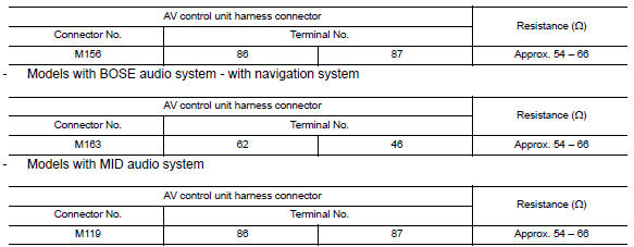
2.CHECK HARNESS FOR OPEN CIRCUIT
- Disconnect the connector of AV control unit.
- Check the resistance between the AV control unit harness connector
terminals.
- Models with BOSE audio system - without navigation system
3.CHECK POWER SUPPLY AND GROUND CIRCUIT
Check the power supply and the ground circuit of the AV control unit. Refer to the following.
- Models without BOSE audio with color display: AV-231, "AV CONTROL UNIT : Diagnosis Procedure" - Models with BOSE audio with color display: AV-388, "AV CONTROL UNIT : Diagnosis Procedure" - Models with BOSE audio with color display with navigation system: AV-571, "AV CONTROL UNIT : Diagnosis Procedure"
 M&A branch line circuit
Diagnosis Procedure
1.CHECK CONNECTOR
Turn the ignition switch OFF.
Disconnect the battery cable from the negative terminal.
Check the terminals and connectors of the combination meter for
...
 HVAC branch line circuit
Diagnosis Procedure
1.CHECK CONNECTOR
Turn the ignition switch OFF.
Disconnect the battery cable from the negative terminal.
Check the terminals and connectors of the A/C auto amp. for
dam ...
Other materials:
Sunroof unit assembly
Inspection and Adjustment
INSPECTION
Wind Deflector
Open glass lid assembly fully.
Visually check for proper installation, damaged/deteriorated
components, or foreign objects within mechanism.
Correct as required for
smooth operation.
Check for grease at the wind deflector arm ( ...
Seatback pockets
The seatback pockets are located on the back of
the driver's and passenger's seats. The pockets
can be used to store maps.
WARNING
To ensure proper operation of the passenger's
NISSAN Advanced Air Bag System,
please observe the following items:
Do not allow a passenger in the rear
se ...
Diagnosis system (TCM)
CONSULT Function
FUNCTION
CONSULT can display each diagnostic item using the diagnostic test modes
shown following.
WORK SUPPORT MODE
Display Item List
Engine Brake Adjustment
CAUTION:
Mode of "+1""0""−1""−2""OFF" can be selected by touching "UP"or
"DOWN" on CONSULT screen ...
Nissan Maxima Owners Manual
- Illustrated table of contents
- Safety-Seats, seat belts and supplemental restraint system
- Instruments and controls
- Pre-driving checks and adjustments
- Monitor, climate, audio, phone and voice recognition systems
- Starting and driving
- In case of emergency
- Appearance and care
- Do-it-yourself
- Maintenance and schedules
- Technical and consumer information
Nissan Maxima Service and Repair Manual

0.0062