Nissan Maxima Service and Repair Manual: P1553 battery current sensor
Description
The power generation voltage variable control enables fuel consumption to be decreased by reducing the engine load which is caused by the power generation of the generator. The battery current sensor is installed to the battery cable at the negative terminal. The sensor measures the charging/discharging current of the battery.
Based on the sensor signal, ECM judges whether or not the power generation voltage variable control is performed. When performing the power generation voltage variable control, ECM calculates the target power generation voltage based on the sensor signal. And ECM sends the calculated value as the power generation command value to IPDM E/R. For the details of the power generation voltage variable control, refer to CHG-8, "System Description".
CAUTION: Never connect the electrical component or the ground wire directly to the battery terminal. The connection causes the malfunction of the power generation voltage variable control, and then the battery discharge may occur.
DTC Logic
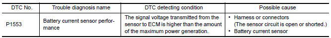
DTC DETECTION LOGIC
NOTE: If DTC P1553 is displayed with DTC P0643, first perform the trouble diagnosis for DTC P0643. Refer to EC-394, "DTC Logic".
DTC CONFIRMATION PROCEDURE
1.PRECONDITIONING
If DTC Confirmation Procedure has been previously conducted, always perform the following before conducting the next test.
- Turn ignition switch OFF and wait at least 10 seconds.
- Turn ignition switch ON.
- Turn ignition switch OFF and wait at least 10 seconds.
TESTING CONDITION: Before performing the following procedure, confirm that battery voltage is more than 8 V at idle.
2.PERFORM DTC CONFIRMATION PROCEDURE
- Start engine and wait at least 10 seconds.
- Check 1st trip DTC.
Diagnosis Procedure
1.CHECK GROUND CONNECTION
- Turn ignition switch OFF.
- Check ground connection E9.
2.CHECK BATTERY CURRENT SENSOR POWER SUPPLY CIRCUIT
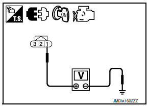
- Disconnect battery current sensor harness connector.
- Turn ignition switch ON.
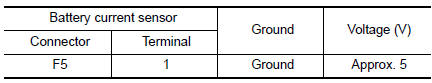
- Check the voltage between battery current sensor harness connector and ground.
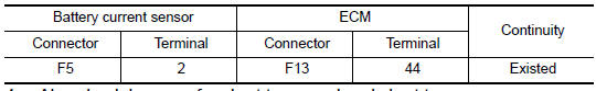
3.CHECK BATTERY CURRENT SENSOR GROUND CIRCUIT FOR OPEN AND SHORT
- Turn ignition switch OFF.
- Disconnect ECM harness connector.
- Check the continuity between battery current sensor harness connector and ECM harness connector.
- Also check harness for short to ground and short to power.
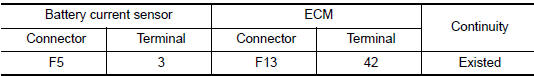
4.CHECK BATTERY CURRENT SENSOR INPUT SIGNAL CIRCUIT FOR OPEN AND SHORT
- Check the continuity between battery current sensor harness connector and ECM harness connector.
- Also check harness for short to ground and short to power
5.CHECK BATTERY CURRENT SENSOR
6.CHECK INTERMITTENT INCIDENT
Component Inspection
1.CHECK BATTERY CURRENT SENSOR
- Turn ignition switch OFF.
- Reconnect harness connectors disconnected.
- Disconnect battery negative cable (1).
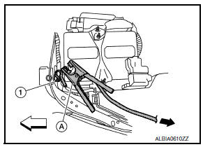
 : Vehicle front
 : To body ground
- Install jumper cable (A) between battery negative terminal and body ground.
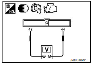
- Turn ignition switch ON.
- Check the voltage between ECM harness connector terminals under the following conditions.
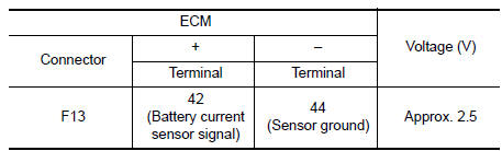
Before measuring the terminal voltage, confirm that the battery is fully charged.
 P1551, P1552 battery current sensor
Description
The power generation voltage variable control enables fuel consumption to be
decreased by reducing the
engine load which is caused by the power generation of the generator. The
batt ...
 P1554 battery current sensor
Description
The power generation voltage variable control enables fuel consumption to be
decreased by reducing the
engine load which is caused by the power generation of the generator. The
batt ...
Other materials:
Center speaker
Description
The AV control unit sends audio signals to the BOSE speaker amp. The BOSE
speaker amp. amplifies the
audio signals before sending them to the center speaker using the audio signal
circuits.
Diagnosis Procedure
1.CONNECTOR CHECK
Check the AV control unit, BOSE speaker amp. and s ...
Battery
Keep the battery surface clean and dry.
Clean the battery with a solution of baking
soda and water.
Make certain the terminal connections are
clean and securely tightened.
If the vehicle is not to be used for 30 days or
longer, disconnect the negative (-) battery
terminal cable to ...
M&A branch line circuit
Diagnosis Procedure
1.CHECK CONNECTOR
Turn the ignition switch OFF.
Disconnect the battery cable from the negative terminal.
Check the terminals and connectors of the combination meter for
damage, bend and loose connection
(unit side and connector side).
2.CHECK HARNESS FOR OPEN CI ...
Nissan Maxima Owners Manual
- Illustrated table of contents
- Safety-Seats, seat belts and supplemental restraint system
- Instruments and controls
- Pre-driving checks and adjustments
- Monitor, climate, audio, phone and voice recognition systems
- Starting and driving
- In case of emergency
- Appearance and care
- Do-it-yourself
- Maintenance and schedules
- Technical and consumer information
Nissan Maxima Service and Repair Manual

0.0062