Nissan Maxima Service and Repair Manual: P1554 battery current sensor
Description
The power generation voltage variable control enables fuel consumption to be decreased by reducing the engine load which is caused by the power generation of the generator. The battery current sensor is installed to the battery cable at the negative terminal. The sensor measures the charging/discharging current of the battery.
Based on the sensor signal, ECM judges whether or not the power generation voltage variable control is performed. When performing the power generation voltage variable control, ECM calculates the target power generation voltage based on the sensor signal. And ECM sends the calculated value as the power generation command value to IPDM E/R. For the details of the power generation voltage variable control, refer to CHG-8, "System Description".
CAUTION: Never connect the electrical component or the ground wire directly to the battery terminal. The connection causes the malfunction of the power generation voltage variable control, and then the battery discharge may occur.
DTC Logic
DTC DETECTION LOGIC
NOTE: If DTC P1554 is displayed with DTC P0643, first perform the trouble diagnosis for DTC P0643. Refer to EC-394, "DTC Logic".
DTC CONFIRMATION PROCEDURE
1.PERFORM COMPONENT FUNCTION CHECK
Perform component function check. Refer to EC-423, "Component Function Check".
NOTE: Use component function check to check the overall function of the battery current sensor circuit. During this check, a 1st trip DTC might not be confirmed.
Component Function Check
1.PRECONDITIONING
TESTING CONDITION:
- Before performing the following procedure, confirm that battery voltage is more than 12.8 V at idle.
- Before performing the following procedure, confirm that all load switches and A/C switch are turned OFF.
2.PERFORM COMPONENT FUNCTION CHECK
With CONSULT
- Start engine and let it idle.
- Select "BAT CUR SEN" in "DATA MONITOR" mode with CONSULT.
- Check "BAT CUR SEN" indication for 10 seconds.
"BAT CUR SEN" should be above 2,300 mV at least once.
Without CONSULT
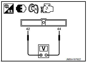
- Start engine and let it idle.
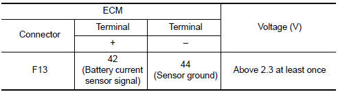
- Check voltage between ECM harness connector terminals under the following conditions.
Diagnosis Procedure
1.CHECK GROUND CONNECTION
- Turn ignition switch OFF.
- Check ground connection E9. Refer
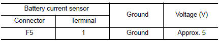
2.CHECK BATTERY CURRENT SENSOR POWER SUPPLY CIRCUIT
- Disconnect battery current sensor harness connector.
- Turn ignition switch ON.
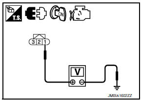
- Check the voltage between battery current sensor harness connector and ground.
3.CHECK BATTERY CURRENT SENSOR GROUND CIRCUIT FOR OPEN AND SHORT
- Turn ignition switch OFF.
- Disconnect ECM harness connector.
- Check the continuity between battery current sensor harness connector and ECM harness connector.
- Also check harness for short to ground and short to power.
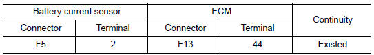
4.CHECK BATTERY CURRENT SENSOR INPUT SIGNAL CIRCUIT FOR OPEN AND SHORT
- Check the continuity between battery current sensor harness connector and ECM harness connector.
- Also check harness for short to ground and short to power.
5.CHECK BATTERY CURRENT SENSOR
6.CHECK INTERMITTENT INCIDENT
Component Inspection
1.CHECK BATTERY CURRENT SENSOR
- Turn ignition switch OFF.
- Reconnect harness connectors disconnected.
- Disconnect battery negative cable (1).
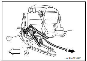
 : Vehicle front
 : To body ground
- Install jumper cable (A) between battery negative terminal and body ground.
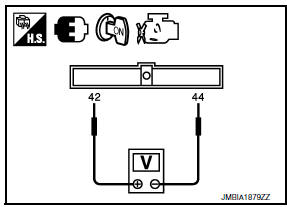
- Turn ignition switch ON.
- Check the voltage between ECM harness connector terminals under the following conditions.
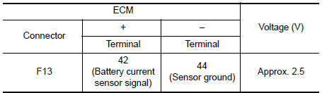
Before measuring the terminal voltage, confirm that the battery is fully charged.
 P1553 battery current sensor
Description
The power generation voltage variable control enables fuel consumption to be
decreased by reducing the
engine load which is caused by the power generation of the generator. The
batt ...
 P1564 ASCD steering switch
Description
ASCD steering switch has variant values of electrical resistance for each
button. ECM reads voltage variation
of switch, and determines which button is operated.
Refer to EC-68, &q ...
Other materials:
IPDM-E branch line circuit
Diagnosis Procedure
1.CHECK CONNECTOR
Turn the ignition switch OFF.
Disconnect the battery cable from the negative terminal.
Check the terminals and connectors of the IPDM E/R for damage,
bend and loose connection (unit side
and connector side).
2.CHECK HARNESS FOR OPEN CIRCUIT
...
Condenser
CONDENSER
CONDENSER : Removal and Installation
REMOVAL
Discharge the refrigerant. Refer to HA-28, "Recycle Refrigerant".
Remove the RH hoodledge cover.
Remove the front bumper fascia. Refer to EXT-16, "Removal and
Installation".
Disconnect the high-pressure pipe from the condenser pip ...
Variable voltage control system
CAUTION
Do not ground accessories directly to
the battery terminal. Doing so will bypass
the variable voltage control system
and the vehicle battery may not
charge completely.
Use electrical accessories with the engine
running to avoid discharging the
vehicle battery.
Your v ...
Nissan Maxima Owners Manual
- Illustrated table of contents
- Safety-Seats, seat belts and supplemental restraint system
- Instruments and controls
- Pre-driving checks and adjustments
- Monitor, climate, audio, phone and voice recognition systems
- Starting and driving
- In case of emergency
- Appearance and care
- Do-it-yourself
- Maintenance and schedules
- Technical and consumer information
Nissan Maxima Service and Repair Manual

0.0062