Nissan Maxima Service and Repair Manual: P1564 ASCD steering switch
Description
ASCD steering switch has variant values of electrical resistance for each button. ECM reads voltage variation of switch, and determines which button is operated.
Refer to EC-68, "System Diagram" for the ASCD function.
DTC Logic
DTC DETECTION LOGIC
NOTE: If DTC P1564 is displayed with DTC P0605, first perform the trouble diagnosis for DTC P0605. Refer to EC-391, "DTC Logic".
DTC CONFIRMATION PROCEDURE
1.PRECONDITIONING
If DTC Confirmation Procedure has been previously conducted, always perform the following before conducting the next test.
- Turn ignition switch OFF and wait at least 10 seconds.
- Turn ignition switch ON.
- Turn ignition switch OFF and wait at least 10 seconds.
2.PERFORM DTC CONFIRMATION PROCEDURE
- Turn ignition switch ON and wait at least 10 seconds.
- Press MAIN switch for at least 10 seconds, then release it and wait at least 10 seconds.
- Press CANCEL switch for at least 10 seconds, then release it and wait at least 10 seconds.
- Press RESUME/ACCELERATE switch for at least 10 seconds, then release it and wait at least 10 seconds.
- Press SET/COAST switch for at least 10 seconds, then release it and wait at least 10 seconds.
- Check DTC.
Diagnosis Procedure
1.CHECK GROUND CONNECTION
- Turn ignition switch OFF.
- Check ground connection E9.
2.CHECK ASCD STEERING SWITCH CIRCUIT
With CONSULT
- Turn ignition switch ON.
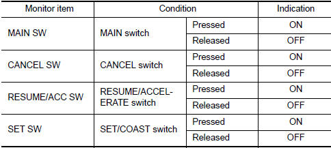
- Select "MAIN SW", "CANCEL SW", "RESUME/ACC SW" and "SET SW" in "DATA MONITOR" mode with CONSULT.
- Check each item indication under the following conditions
Without CONSULT
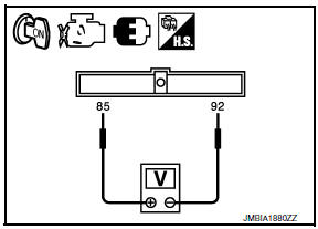
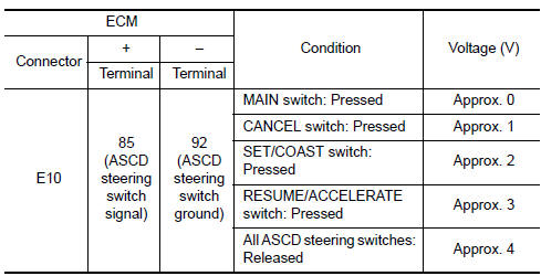
- Turn ignition switch ON.
- Check the voltage between ECM harness connector terminals under the following conditions.
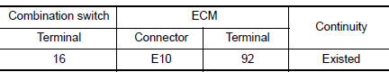
3.CHECK ASCD STEERING SWITCH GROUND CIRCUIT FOR OPEN AND SHORT
- Turn ignition switch OFF.
- Disconnect ECM harness connector.
- Disconnect combination switch harness connector.
- Check the continuity between combination switch and ECM harness connector.
- Also check harness for short to ground and short to power.
4.DETECT MALFUNCTIONING PART
- Check the following. Harness connectors E30, M11
- Combination switch (spiral cable)
- Harness for open and short between ECM and combination switch
5.CHECK ASCD STEERING SWITCH INPUT SIGNAL CIRCUIT FOR OPEN AND SHORT
- Check the continuity between combination switch and ECM harness connector.
- Also check harness for short to ground and short to power
6.DETECT MALFUNCTIONING PART
Check the following.
- Harness connectors E30, M1
- Combination switch (spiral cable)
- Harness for open and short between ECM and combination switch
7.CHECK ASCD STEERING SWITCH
8.CHECK INTERMITTENT INCIDENT
Component Inspection
1.CHECK ASCD STEERING SWITCH
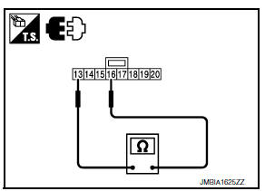
- Turn ignition switch OFF.
- Disconnect combination switch (spiral cable) harness connector.
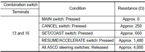
- Check resistance between combination switch harness connector terminals as per the following.
 P1554 battery current sensor
Description
The power generation voltage variable control enables fuel consumption to be
decreased by reducing the
engine load which is caused by the power generation of the generator. The
batt ...
 P1572 ASCD brake switch
Description
When the brake pedal is depressed, ASCD brake switch is turned OFF and stop
lamp switch is turned ON.
ECM detects the state of the brake pedal by those two types of input (ON/OFF
s ...
Other materials:
Front fog lamp system
Wiring Diagram
...
How to park with predicted course lines
WARNING
If the tires are replaced with different
sized tires, the predicted course lines
may be displayed incorrectly.
On a snow-covered or slippery road,
there may be a difference between the
predicted course line and the actual
course line.
If the battery is disconnected or becomes
discha ...
Control system
System Diagram
System Description
The CVT senses vehicle operating conditions through various sensors. It
always controls the optimum shift
position and reduces shifting and lock-up shocks.
TCM FUNCTION
The function of the TCM is to:
Receive input signals sent from various switch ...
Nissan Maxima Owners Manual
- Illustrated table of contents
- Safety-Seats, seat belts and supplemental restraint system
- Instruments and controls
- Pre-driving checks and adjustments
- Monitor, climate, audio, phone and voice recognition systems
- Starting and driving
- In case of emergency
- Appearance and care
- Do-it-yourself
- Maintenance and schedules
- Technical and consumer information
Nissan Maxima Service and Repair Manual

0.0057