Nissan Maxima Service and Repair Manual: P1572 ASCD brake switch
Description
When the brake pedal is depressed, ASCD brake switch is turned OFF and stop lamp switch is turned ON.
ECM detects the state of the brake pedal by those two types of input (ON/OFF signal).
Refer to EC-68, "System Diagram" for the ASCD function.
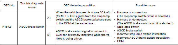
DTC Logic
DTC DETECTION LOGIC
NOTE:
- If DTC P1572 is displayed with DTC P0605, first perform the trouble diagnosis for DTC P0605. Refer to EC-391, "DTC Logic".
- This self-diagnosis has the one trip detection logic. When
malfunction A is detected, DTC is not
stored in ECM memory. And in that case, 1st trip DTC and 1st trip freeze
frame data are displayed.
1st trip DTC is erased when ignition switch is turned OFF. And even when malfunction A is detected in two consecutive trips, DTC is not stored in ECM memory.
DTC CONFIRMATION PROCEDURE
1.PRECONDITIONING
If DTC Confirmation Procedure has been previously conducted, always perform the following before conducting the next test.
- Turn ignition switch OFF and wait at least 10 seconds.
- Turn ignition switch ON.
- Turn ignition switch OFF and wait at least 10 seconds.
NOTE: The procedure for malfunction B is not described. It takes an extremely long time to complete the procedure for malfunction B. By performing the procedure for malfunction A, the condition that causes malfunction B can be detected.
2.PERFORM DTC CONFIRMATION PROCEDURE
With CONSULT
- Start engine (VDC switch OFF).
- Select "DATA MONITOR" mode with CONSULT.
- Press MAIN switch and check that CRUISE lamp illuminate.
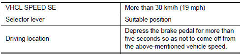
- Drive the vehicle for at least 5 consecutive seconds under the following conditions.
CAUTION: Always drive vehicle at a safe speed.
NOTE: This procedure may be conducted with the drive wheels lifted in the shop or by driving the vehicle.
If a road test is expected to be easier, it is unnecessary to lift the vehicle.

- Check 1st trip DTC.
With GST
Follow the procedure "With CONSULT" above.
3.PERFORM DTC CONFIRMATION PROCEDURE
With CONSULT
- Drive the vehicle for at least 5 consecutive seconds under the following conditions.
CAUTION: Always drive vehicle at a safe speed.
NOTE: This procedure may be conducted with the drive wheels lifted in the shop or by driving the vehicle.
If a road test is expected to be easier, it is unnecessary to lift the vehicle.
- Check 1st trip DTC.
With GST
Follow the procedure "With CONSULT" above.
Diagnosis Procedure
Regarding Wiring Diagram information, refer to EC-554, "Wiring Diagram".
1.CHECK OVERALL FUNCTION-I
With CONSULT
- Turn ignition switch ON.
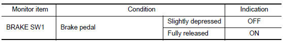
- Select "BRAKE SW1" in "DATA MONITOR" mode with CONSULT.
- Check "BRAKE SW1" indication under the following conditions.
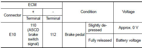
Without CONSULT
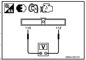
- Turn ignition switch ON.
- Check the voltage between ECM harness connectors.
2.CHECK OVERALL FUNCTION-II
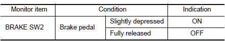
With CONSULT
Check "BRAKE SW2" indication in "DATA MONITOR" mode.
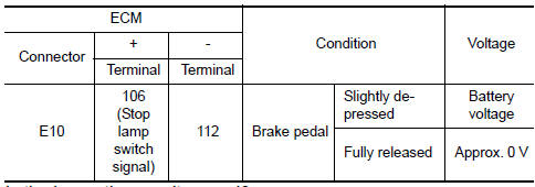
Without CONSULT
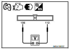
Check the voltage between ECM harness connectors.
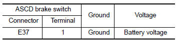
3.CHECK ASCD BRAKE SWITCH POWER SUPPLY CIRCUIT
- Turn ignition switch OFF.
- Disconnect ASCD brake switch harness connector.
- Turn ignition switch ON.
- Check the voltage between ASCD brake switch harness connector and ground.
4.DETECT MALFUNCTIONING PART
Check the following.
- Fuse block (J/B) connector E6
- Junction block harness connectors E44, E46
- 10 A fuse (No. 3)
- Harness for open or short between ASCD brake switch and fuse
5.CHECK ASCD BRAKE SWITCH INPUT SIGNAL CIRCUIT FOR OPEN AND SHORT
- Turn ignition switch OFF.
- Disconnect ECM harness connector.
- Check the continuity between ASCD brake switch harness connector and ECM harness connector.
- Also check harness for short to ground and short to power.
6.DETECT MALFUNCTIONING PART
Check the following.
- Junction block connectors E45, E46
- Harness for open or short between ASCD brake switch and ECM
7.CHECK ASCD BRAKE SWITCH
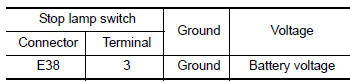
8.CHECK STOP LAMP SWITCH POWER SUPPLY CIRCUIT
- Turn ignition switch OFF.
- Disconnect stop lamp switch harness connector.
- Check the voltage between stop lamp switch harness connector and ground.
9.DETECT MALFUNCTIONING PART
Check the following.
- Fuse block (J/B) connector E6
- 10 A fuse (No. 7)
- Harness for open or short between stop lamp switch and battery
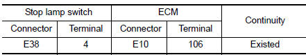
10.CHECK STOP LAMP SWITCH INPUT SIGNAL CIRCUIT FOR OPEN AND SHORT
- Disconnect ECM harness connector.
- Check the continuity between stop lamp switch harness connector and ECM harness connector
- Also check harness for short to ground and short to power.
11.DETECT MALFUNCTIONING PART
Check the following.
- Fuse block (J/B) connector E6
- Junction block connectors E44, E45
- Harness for open or short between stop lamp switch and ECM
12.CHECK STOP LAMP SWITCH
13.CHECK INTERMITTENT INCIDENT
Component Inspection (ASCD Brake Switch)
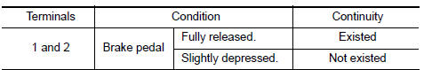
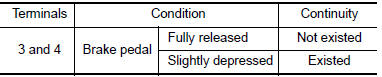
1.CHECK ASCD BRAKE SWITCH-I
- Turn ignition switch OFF.
- Disconnect ASCD brake switch harness connector.
- Check the continuity between ASCD brake switch terminals under the following conditions.
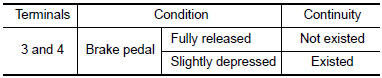
2.CHECK ASCD BRAKE SWITCH-II
- Adjust ASCD brake switch installation. Refer to BR-18, "Removal and Installation".
- Check the continuity between ASCD brake switch terminals under the following conditions.
Component Inspection (Stop Lamp Switch)
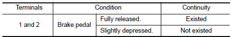
1.CHECK STOP LAMP SWITCH-I
- Turn ignition switch OFF.
- Disconnect stop lamp switch harness connector.
- Check harness continuity between stop lamp switch terminals under the following conditions.
2.CHECK STOP LAMP SWITCH-II
- Adjust stop lamp switch installation. Refer to BR-14, "Inspection and Adjustment".
- Check harness continuity between stop lamp switch terminals under the following conditions.
 P1564 ASCD steering switch
Description
ASCD steering switch has variant values of electrical resistance for each
button. ECM reads voltage variation
of switch, and determines which button is operated.
Refer to EC-68, &q ...
 P1574 ASCD vehicle speed sensor
Description
The ECM receives two vehicle speed signals via the CAN communication line.
One is sent from combination
meter, and the other is from TCM (Transmission control module). The ECM uses
...
Other materials:
Hazard switch
Component Function Check
1.CHECK HAZARD SWITCH SIGNAL BY CONSULT
CONSULT DATA MONITOR
Turn ignition switch ON.
Select "HAZARD SW" of BCM (FLASHER) DATA MONITOR item.
With operating the hazard switch, check the monitor status.
Diagnosis Procedure
1.CHECK HAZARD SWITCH SIGNAL INPUT
...
P0615 starter relay
Description
TCM controls starter relay in IPDM E/R.
TCM switches starter relay ON at "P" or "N" position and allows to
crank engine.
Then it prohibits cranking other than at "P" or "N" position.
DTC Logic
DTC DETECTION LOGIC
DTC CONFIRMATION PROCEDURE
CAUTION: Al ...
Driving on snow or ice
WARNING
Wet ice (32F, 0C and freezing rain),
very cold snow or ice can be slick and
very hard to drive on. The vehicle will
have much less traction or "grip" under
these conditions. Try to avoid driving on
wet ice until the road is salted or
sanded.
Whatever the condition, drive wi ...
Nissan Maxima Owners Manual
- Illustrated table of contents
- Safety-Seats, seat belts and supplemental restraint system
- Instruments and controls
- Pre-driving checks and adjustments
- Monitor, climate, audio, phone and voice recognition systems
- Starting and driving
- In case of emergency
- Appearance and care
- Do-it-yourself
- Maintenance and schedules
- Technical and consumer information
Nissan Maxima Service and Repair Manual

0.0056