
Nissan Maxima Service and Repair Manual: P1574 ASCD vehicle speed sensor
Description
The ECM receives two vehicle speed signals via the CAN communication line. One is sent from combination meter, and the other is from TCM (Transmission control module). The ECM uses these signals for ASCD control.
Refer to EC-68, "System Diagram" for ASCD functions.
DTC Logic
DTC DETECTION LOGIC
NOTE:
- If DTC P1574 is displayed with DTC UXXXX, first perform the trouble diagnosis for DTC UXXXX.
- If DTC P1574 is displayed with DTC P0500, first perform the trouble diagnosis for DTC P0500. Refer to EC-378, "DTC Logic".
- If DTC P1574 is displayed with DTC P0605, first perform the trouble diagnosis for DTC P0605. Refer to EC-391, "DTC Logic".
- If DTC P1574 is displayed with DTC P0607, first perform the trouble diagnosis for DTC P0607. Refer to EC-393, "DTC Logic".
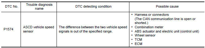
DTC CONFIRMATION PROCEDURE
1.PRECONDITIONING
If DTC Confirmation Procedure has been previously conducted, always perform the following before conducting the next test.
- Turn ignition switch OFF and wait at least 10 seconds.
- Turn ignition switch ON.
- Turn ignition switch OFF and wait at least 10 seconds.
2.PERFORM DTC CONFIRMATION PROCEDURE
- Start engine (VDC switch OFF).
- Drive the vehicle at more than 40 km/h (25 MPH).
CAUTION:
Always drive vehicle at a safe speed.
NOTE: This procedure may be conducted with the drive wheels lifted in the shop or by driving the vehicle.
If a road test is expected to be easier, it is unnecessary to lift the vehicle.
- Check DTC.
Diagnosis Procedure
1.CHECK DTC WITH TCM
Check DTC with TCM.
2.CHECK DTC WITH "ABS ACTUATOR AND ELECTRIC UNIT (CONTROL UNIT)"
3.CHECK COMBINATION METER FUNCTION
P1700 CVT CONTROL SYSTEM
Description
This DTC is displayed with other DTC regarding TCM. Perform the trouble diagnosis for corresponding DTC.
Refer to EC-542, "DTC Index". When this DTC is detected, the ASCD control is canceled.
 P1572 ASCD brake switch
Description
When the brake pedal is depressed, ASCD brake switch is turned OFF and stop
lamp switch is turned ON.
ECM detects the state of the brake pedal by those two types of input (ON/OFF
s ...
 P1715 input speed sensor
Description
ECM receives input speed sensor signal from TCM via the CAN communication
line. ECM uses this signal for
engine control.
DTC Logic
DTC DETECTION LOGIC
NOTE:
If DTC P1715 ...
Other materials:
ECM branch line circuit
Diagnosis Procedure
1.CHECK CONNECTOR
Turn the ignition switch OFF.
Disconnect the battery cable from the negative terminal.
Check the following terminals and connectors for damage, bend and
loose connection (unit side and connector
side).
- Models without automatic drive positione ...
TCM branch line circuit
Diagnosis Procedure
1.CHECK CONNECTOR
Turn the ignition switch OFF.
Disconnect the battery cable from the negative terminal.
Check the following terminals and connectors for damage, bend and
loose connection (unit side and connector
side).
TCM
Harness connector F1
Harness con ...
Power consumption control system
System Diagram
System Description
OUTLINE
IPDM E/R incorporates a power consumption control function that
reduces the power consumption according
to the vehicle status.
IPDM E/R changes its status (control mode) with the sleep wake up
signal received from BCM via CAN communicati ...
Nissan Maxima Owners Manual
- Illustrated table of contents
- Safety-Seats, seat belts and supplemental restraint system
- Instruments and controls
- Pre-driving checks and adjustments
- Monitor, climate, audio, phone and voice recognition systems
- Starting and driving
- In case of emergency
- Appearance and care
- Do-it-yourself
- Maintenance and schedules
- Technical and consumer information
Nissan Maxima Service and Repair Manual

0.0134