Nissan Maxima Service and Repair Manual: P1715 input speed sensor
Description
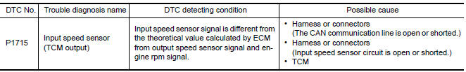
ECM receives input speed sensor signal from TCM via the CAN communication line. ECM uses this signal for engine control.
DTC Logic
DTC DETECTION LOGIC
NOTE:
- If DTC P1715 is displayed with DTC UXXXX first perform the trouble diagnosis for DTC UXXXX. Refer to EC-161, "DTC Logic".
- If DTC P1715 is displayed with DTC P0335, first perform the trouble diagnosis for DTC P0335. Refer to EC-296, "DTC Logic".
- If DTC P1715 is displayed with DTC P0340, P0345, first perform the trouble diagnosis for DTC P0340, P0345. Refer to EC-300, "DTC Logic".
- If DTC P1715 is displayed with DTC P0605, first perform the trouble diagnosis for DTC P0605. Refer to EC-391, "DTC Logic".
- If DTC P1715 is displayed with DTC P0607, first perform the trouble diagnosis for DTC P0607. Refer to EC-393, "DTC Logic".
DTC CONFIRMATION PROCEDURE
1.PRECONDITIONING
If DTC Confirmation Procedure has been previously conducted, always perform the following before conducting the next test.
- Turn ignition switch OFF and wait at least 10 seconds.
- Turn ignition switch ON.
- Turn ignition switch OFF and wait at least 10 seconds.
2.PERFORM DTC CONFIRMATION PROCEDURE
- Start engine.
- Drive vehicle at a speed of more than 50 km/h (31 MPH) for at least 5 seconds.
- Check 1st trip DTC.
Diagnosis Procedure
1.CHECK DTC WITH TCM
Check DTC with TCM.
2.REPLACE TCM
Replace TCM.
 P1574 ASCD vehicle speed sensor
Description
The ECM receives two vehicle speed signals via the CAN communication line.
One is sent from combination
meter, and the other is from TCM (Transmission control module). The ECM uses
...
 P1720 VSS
Description
ECM receives two vehicle speed signals via the CAN communication line. One is
sent from "ABS actuator and
electric unit (control unit)" via the combination meter, and the other is fro ...
Other materials:
A/C switch assembly signal circuit
Diagnosis Procedure
1.CHECK WITH SELF-DIAGNOSIS FUNCTION OF CONSULT
Using CONSULT, perform "SELF-DIAGNOSIS RESULTS" of HVAC.
Check if any DTC No. is displayed in the self-diagnosis results.
NOTE:
If DTC is displayed along with DTC U1000 or U1010, first diagnose the DTC U1000
or U1010.
...
Wiring diagram
AIR CONDITIONER CONTROL
Wiring Diagram - With Color Display
...
System maintenance
CAUTION
Do not use alcohol, benzine or thinner
to clean the camera. This will cause
discoloration.
Do not damage the cameras as the
monitor screen may be adversely
affected.
If dirt, rain or snow accumulates on any of the
cameras 1 , the Around View Monitor may not
display obj ...
Nissan Maxima Owners Manual
- Illustrated table of contents
- Safety-Seats, seat belts and supplemental restraint system
- Instruments and controls
- Pre-driving checks and adjustments
- Monitor, climate, audio, phone and voice recognition systems
- Starting and driving
- In case of emergency
- Appearance and care
- Do-it-yourself
- Maintenance and schedules
- Technical and consumer information
Nissan Maxima Service and Repair Manual

0.0064