Nissan Maxima Service and Repair Manual: P0603 ECM power supply
Description
Battery voltage is supplied to the ECM even when the ignition switch is turned OFF for the ECM memory function of the DTC memory, the air-fuel ratio feedback compensation value memory, the idle air volume learning value memory, etc.
DTC Logic
DTC DETECTION LOGIC
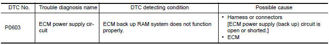
DTC CONFIRMATION PROCEDURE
1.PRECONDITIONING
If DTC Confirmation Procedure has been previously conducted, always perform the following before conducting the next test.
- Turn ignition switch OFF and wait at least 10 seconds.
- Turn ignition switch ON.
- Turn ignition switch OFF and wait at least 10 seconds.
2.PERFORM DTC CONFIRMATION PROCEDURE
- Turn ignition switch ON and wait at least 10 second.
- Turn ignition switch OFF and wait at least 5 minutes.
- Turn ignition switch ON, wait at least 10 seconds.
- Repeat steps 2 and 3 for five times.
- Check 1st trip DTC.
Diagnosis Procedure
1.CHECK ECM POWER SUPPLY
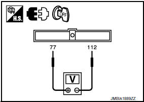
- Turn ignition switch OFF.
- Disconnect ECM harness connector.
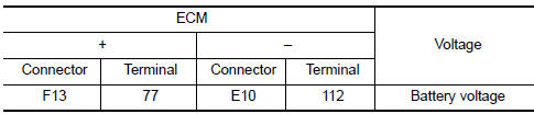
- Check the voltage between ECM harness connector and ground.
2.DETECT MALFUNCTIONING PART
Check the following.
- 15 A fuse (No. 42)
- IPDM E/R harness connector F10
- Harness for open or short between ECM and battery
3.CHECK INTERMITTENT INCIDENT
4.PERFORM DTC CONFIRMATION PROCEDURE
- Turn ignition switch ON.
- Erase DTC.
- Perform DTC CONFIRMATION PROCEDURE.
5.REPLACE ECM
- Replace ECM.
 P0550 PSP sensor
Description
Power steering pressure (PSP) sensor is installed to the power steering
high-pressure tube and detects a
power steering load.
This sensor is a potentiometer which transforms the po ...
 P0605 ECM
Description
The ECM consists of a microcomputer and connectors for signal
input and output and for power supply. The ECM controls the engine
DTC Logic
DTC DETECTION LOGIC
DTC CONFIRMATIO ...
Other materials:
System temporarily unavailable
Condition A
When the radar sensor picks up interference
from another radar source, making it impossible
to detect a vehicle ahead, the PFCW system is
automatically turned off.
The FEB system warning light (orange) will illuminate.
Action to take
When the above conditions no longer exist, th ...
Symptom diagnosis
UNBALANCE STEERING WHEEL TURNING FORCE (TORQUE VARIATION)
Description
Hard steering when fully turning the steering wheel.
Light steering when driving at a high speed.
Diagnosis Procedure
1.CHECK SYSTEM FOR POWER SUPPLY AND GROUND
Perform trouble diagnosis for power supply and ground cir ...
Blower unit
BLOWER UNIT
BLOWER UNIT : Removal and Installation
COMPONENTS
Heater and cooling unit
Blower unit Front
REMOVAL
Remove the heater and cooling unit assembly. Refer to HA-47,
"HEATER & COOLING UNIT ASSEMBLY : Removal and Installation".
Disconnect the harness connector from ...
Nissan Maxima Owners Manual
- Illustrated table of contents
- Safety-Seats, seat belts and supplemental restraint system
- Instruments and controls
- Pre-driving checks and adjustments
- Monitor, climate, audio, phone and voice recognition systems
- Starting and driving
- In case of emergency
- Appearance and care
- Do-it-yourself
- Maintenance and schedules
- Technical and consumer information
Nissan Maxima Service and Repair Manual

0.0066