Nissan Maxima Service and Repair Manual: P0605 ECM
Description
The ECM consists of a microcomputer and connectors for signal input and output and for power supply. The ECM controls the engine
DTC Logic
DTC DETECTION LOGIC
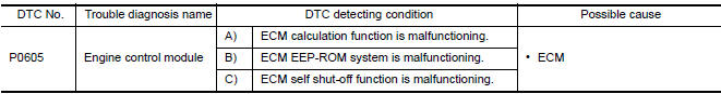
DTC CONFIRMATION PROCEDURE
1.PRECONDITIONING
If DTC Confirmation Procedure has been previously conducted, always perform the following before conducting the next test.
- Turn ignition switch OFF and wait at least 10 seconds.
- Turn ignition switch ON.
- Turn ignition switch OFF and wait at least 10 seconds.
2.PERFORM DTC CONFIRMATION PROCEDURE FOR MALFUNCTION A
- Turn ignition switch ON.
- Check 1st trip DTC.
3.PERFORM DTC CONFIRMATION PROCEDURE FOR MALFUNCTION B
- Turn ignition switch ON and wait at least 1 second.
- Turn ignition switch OFF, wait at least 10 seconds, and then turn it ON.
- Check 1st trip DTC.
4.PERFORM DTC CONFIRMATION PROCEDURE FOR MALFUNCTION C
- Turn ignition switch ON and wait at least 1 second.
- Turn ignition switch OFF, wait at least 10 seconds, and then turn it ON.
- Repeat step 2 for 32 times.
- Check 1st trip DTC.
Diagnosis Procedure
1.INSPECTION START
- Turn ignition switch ON.
- Erase DTC.
- Perform DTC CONFIRMATION PROCEDURE.
2.REPLACE ECM
- Replace ECM
 P0603 ECM power supply
Description
Battery voltage is supplied to the ECM even when the ignition switch
is turned OFF for the ECM memory function of the DTC memory, the
air-fuel ratio feedback compensation value me ...
 P0607 ECM
Description
CAN (Controller Area Network) is a serial communication line for real time
application. It is an on-vehicle multiplex
communication line with high data communication speed and excelle ...
Other materials:
P2122, P2123 APP sensor
Description
The accelerator pedal position sensor is installed on the upper end
of the accelerator pedal assembly. The sensor detects the accelerator
position and sends a signal to the ECM.
Accelerator pedal position sensor has two sensors. These sensors
are a kind of potentiometer which t ...
Programming HomeLink
If you have any questions or are having difficulty
programming your HomeLink buttons, refer to
the HomeLink web site at: www.homelink.com
or call 1-800-355-3515.
NOTE:
Place the ignition switch in the ACC position
when programming HomeLink. It is
also recommended that a new battery be
placed ...
P0127 IAT sensor
Description
The intake air temperature sensor is built-into the mass air flow sensor
(1). The sensor detects intake air temperature and transmits a
signal to the ECM.
The temperature sensing unit uses a thermistor which is sensitive to
the change in temperature. Electrical resistance o ...
Nissan Maxima Owners Manual
- Illustrated table of contents
- Safety-Seats, seat belts and supplemental restraint system
- Instruments and controls
- Pre-driving checks and adjustments
- Monitor, climate, audio, phone and voice recognition systems
- Starting and driving
- In case of emergency
- Appearance and care
- Do-it-yourself
- Maintenance and schedules
- Technical and consumer information
Nissan Maxima Service and Repair Manual

0.006