Nissan Maxima Service and Repair Manual: P2100, P2103 throttle control motor relay
Description
Power supply for the throttle control motor is provided to the ECM via the throttle control motor relay. The throttle control motor relay is controlled ON/OFF by the ECM. When the ignition switch is turned ON, the ECM sends an ON signal to throttle control motor relay and battery voltage is provided to the ECM. When the ignition switch is turned OFF, the ECM sends an OFF signal to throttle control motor relay and battery voltage is not provided to the ECM.
DTC Logic
DTC DETECTION LOGIC
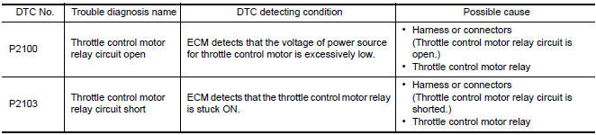
DTC CONFIRMATION PROCEDURE
1.PRECONDITIONING
If DTC Confirmation Procedure has been previously conducted, always perform the following before conducting the next test.
- Turn ignition switch OFF and wait at least 10 seconds.
- Turn ignition switch ON.
- Turn ignition switch OFF and wait at least 10 seconds.
TESTING CONDITION: Before performing the following procedure, confirm that battery voltage is more than 8 V.
2.PERFORM DTC CONFIRMATION PROCEDURE FOR DTC P2100
- Turn ignition switch ON and wait at least 2 seconds.
- Start engine and let it idle for 5 seconds.
- Check DTC.
3.PERFORM DTC CONFIRMATION PROCEDURE FOR DTC P2103
- Turn ignition switch ON and wait at least 1 second.
- Check DTC.
Diagnosis Procedure
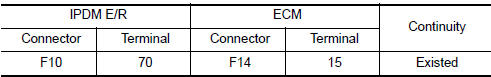
1.CHECK THROTTLE CONTROL MOTOR RELAY POWER SUPPLY CIRCUIT
- Turn ignition switch OFF.
- Disconnect ECM harness connector.
- Disconnect IPDM E/R harness connector.
- Check the continuity between IPDM E/R harness connector and ECM harness connector.
- Also check harness for short to ground and short to power.
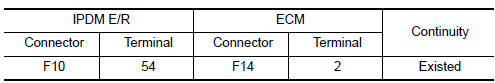
2.CHECK THROTTLE CONTROL MOTOR RELAY INPUT SIGNAL CIRCUIT-II
- Check the continuity between IPDM E/R harness connector and ECM harness connector.
- Also check harness for short to ground and short to power.
3.CHECK FUSE
- Disconnect 15 A fuse (No. 43) from IPDM E/R.
- Check if 15 A fuse is blown.
4.CHECK INTERMITTENT INCIDENT
 P2096, P2097, P2098, P2099 A/F sensor 1
Description
The air fuel ratio (A/F) sensor 1 is a planar one-cell limit current sensor.
The sensor element of the A/F sensor 1 is composed an electrode
layer, which transports ions. It has a he ...
 P2101 electric throttle control function
Description
Electric throttle control actuator consists of throttle control motor,
throttle position sensor, etc.
The throttle control motor is operated by the ECM and it opens and closes the
...
Other materials:
Tel antenna
Removal and Installation
REMOVAL
Disconnect the battery negative terminal. Refer to PG-67, "Removal
and Installation (Battery)".
Remove the rear parcel shelf finisher. Refer to INT-28, "Removal
and Installation".
Remove the Bluetooth antenna screw (A).
Detach the ...
Wiring diagram
IPDM E/R (INTELLIGENT POWER DISTRIBUTION MODULE ENGINE
ROOM)
Wiring Diagram
...
ASCD brake switch
Description
When the brake pedal is depressed, ASCD brake switch is turned OFF and stop
lamp switch is turned ON.
ECM detects the state of the brake pedal by those two types of input (ON/OFF
signal).
Refer to EC-68, "System Diagram" for the ASCD function.
Component Function Che ...
Nissan Maxima Owners Manual
- Illustrated table of contents
- Safety-Seats, seat belts and supplemental restraint system
- Instruments and controls
- Pre-driving checks and adjustments
- Monitor, climate, audio, phone and voice recognition systems
- Starting and driving
- In case of emergency
- Appearance and care
- Do-it-yourself
- Maintenance and schedules
- Technical and consumer information
Nissan Maxima Service and Repair Manual

0.007