
Nissan Maxima Owners Manual: Install
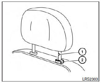
1. Align the head restraint/headrest stalks with the holes in the seat. Make sure that the head restraint/headrest is facing the correct direction. The stalk with the notch (notches) 1 must be installed in the hole with the lock knob 2 .
2. Push and hold the lock knob and push the head restraint/headrest down.
3. Properly adjust the head restraint/headrest before an occupant uses the seating position.
 Remove
Use the following procedure to remove the head
restraint/headrest:
1. Pull the head restraint/headrest up to the
highest position.
2. Push and hold the lock knob.
3. Remove the head restrai ...
 Adjust
For adjustable head restraint/headrest
Adjust the head restraint/headrest so the center
is level with the center of your ears. If your ear
position is still higher than the recommended
alignment ...
Other materials:
Vehicle Dynamic Control (VDC) system
The VDC system uses various sensors to monitor
driver inputs and vehicle motion. Under certain
driving conditions, the VDC system helps to perform
the following functions:
Controls brake pressure to reduce wheel
slip on one slipping drive wheel so power is
transferred to a non slipping dr ...
Diagnosis and repair workflow
Work Flow
OVERALL SEQUENCE
DETAILED FLOW\
1.CHECK SYMPTOM
Check the malfunction symptoms by performing the following items.
Interview the customer to obtain the malfunction information
(conditions and environment when the malfunction occurred).
Check the symptom.
2.SELF-DIAGNOSIS ( ...
BSW system operation
1. Side BSW/RCTA Indicator Light
2. BSW/RCTA Indicator
The BSW system operates above approximately
20 mph (32km/h).
If the radar sensors detect a vehicle in the detection
zone, the side BSW/RCTA indicator light (1)
illuminates. If the turn signal is then activated, the
system chimes (tw ...
Nissan Maxima Owners Manual
- Illustrated table of contents
- Safety-Seats, seat belts and supplemental restraint system
- Instruments and controls
- Pre-driving checks and adjustments
- Monitor, climate, audio, phone and voice recognition systems
- Starting and driving
- In case of emergency
- Appearance and care
- Do-it-yourself
- Maintenance and schedules
- Technical and consumer information
Nissan Maxima Service and Repair Manual

0.0203