Nissan Maxima Owners Manual: Head restraints/headrests
WARNING
Head restraints/headrests supplement the other vehicle safety systems. They may provide additional protection against injury in certain rear end collisions. Adjustable head restraints/headrests must be adjusted properly, as specified in this section.
Check the adjustment after someone else uses the seat. Do not attach anything to the head restraint/headrest stalks or remove the head restraint/headrest. Do not use the seat if the head restraint/headrest has been removed. If the head restraint/headrest was removed, reinstall and properly adjust the head restraint/headrest before an occupant uses the seating position. Failure to follow these instructions can reduce the effectiveness of the head restraints/headrests. This may increase the risk of serious injury or death in a collision.
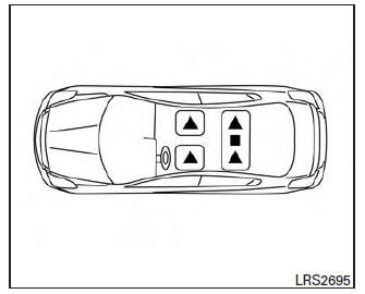
The illustration shows the seating positions equipped with head restraints/headrests.
 Indicates the seating position is
equipped with
a head restraint.
Indicates the seating position is
equipped with
a head restraint.
 Indicates the seating position
is equipped with
a headrest.
Indicates the seating position
is equipped with
a headrest.
+ Indicates the seating position is not equipped with a head restraint or headrest (if applicable).
Your vehicle is equipped with a head restraint/headrest that may be integrated, adjustable or non-adjustable.
Adjustable head restraints/headrests have multiple notches along the stalk(s) to lock them in a desired adjustment position.
The non-adjustable head restraints/headrests have a single locking notch to secure them to the seat frame.
Proper Adjustment:
- For the adjustable type, align the head restraint/headrest so the center of your ear is approximately level with the center of the head restraint/headrest.
- If your ear position is still higher than the recommended alignment, place the head restraint/headrest at the highest position.
If the head restraint/headrest has been removed, ensure that it is reinstalled and locked in place before riding in that designated seating position.
 Folding rear seat
Interior trunk access
The trunk can be accessed from the passenger
side of the rear seat for loading and unloading, as
shown.
1. Move the front passenger seat to the most
forward position.
...
 Adjustable head restraint/headrest components
1. Removable head restraint/headrest
2. Multiple notches
3. Lock knob
4. Stalks
Non-adjustable head restraint/headrest components
1. Removable head restraint/headrest
2. Single notch
3 ...
Other materials:
P0453 evap control system pressure sensor
Description
The EVAP control system pressure sensor detects pressure in the
purge line. The sensor output voltage to the ECM increases as pressure
increases.
DTC Logic
DTC DETECTION LOGIC
DTC CONFIRMATION PROCEDURE
1.PRECONDITIONING
If DTC Confirmation Procedure has been previously ...
Precaution
PRECAUTIONS
Precaution for Supplemental Restraint System (SRS) "AIR BAG" and "SEAT
BELT
PRE-TENSIONER"
The Supplemental Restraint System such as "AIR BAG" and "SEAT BELT
PRE-TENSIONER", used along
with a front seat belt, helps to reduce the risk or severity of injury to ...
AV control unit
Reference Value
VALUES ON THE DIAGNOSIS TOOL
CONSULT data monitor item
TERMINAL LAYOUT
PHYSICAL VALUES
DTC Index
SELF-DIAGNOSIS RESULTS DISPLAY ITEM
...
Nissan Maxima Owners Manual
- Illustrated table of contents
- Safety-Seats, seat belts and supplemental restraint system
- Instruments and controls
- Pre-driving checks and adjustments
- Monitor, climate, audio, phone and voice recognition systems
- Starting and driving
- In case of emergency
- Appearance and care
- Do-it-yourself
- Maintenance and schedules
- Technical and consumer information
Nissan Maxima Service and Repair Manual

0.0056