Nissan Maxima Service and Repair Manual: Basic inspection
DIAGNOSIS AND REPAIR WORKFLOW
Work Flow
OVERALL SEQUENCE
DETAILED FLOW
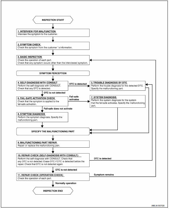
1.INTERVIEW FOR MALFUNCTION
Find out what the customer's concerns are.
2.SYMPTOM CHECK
Verify the symptom from the customer's information.
3.BASIC INSPECTION
Check the operation of each part. Check if any concerns occur other than those mentioned in the customer interview.
4.SELF-DIAGNOSIS WITH CONSULT
Perform the self diagnosis with CONSULT. Check if any DTC is detected.
5.TROUBLE DIAGNOSIS BY DTC
Perform the trouble diagnosis for the detected DTC. Specify the malfunctioning part.
6.FAIL-SAFE ACTIVATION CHECK
Determine if the customer's concern is related to fail-safe activation.
7.SYSTEM DIAGNOSIS
Perform the system diagnosis for the system in which the fail-safe activates. Specify the malfunctioning part.
8.SYMPTOM DIAGNOSIS
Perform the symptom diagnosis. Specify the malfunctioning part.
9.MALFUNCTION PART REPAIR
Repair or replace the malfunctioning part.
10.REPAIR CHECK (SELF-DIAGNOSIS WITH CONSULT)
Perform the self diagnosis with CONSULT. Verify that no DTCs are detected. Erase all DTCs which were detected prior to the repair. Perform the self diagnosis with CONSULT again. Verify that DTC is not detected again.
11.REPAIR CHECK (OPERATION CHECK)
Check the operation of each part.
 Service data and specifications (SDS)
Bulb Specifications
*: Always check with the Parts Department for the latest parts information. ...

Other materials:
AMP on signal circuit
Description
When the audio system is turned on, a voltage signal is supplied from the AV
control unit to the BOSE speaker
amp. When this signal is received, the BOSE speaker amp. will turn on.
Diagnosis Procedure
1.CHECK AMP ON SIGNAL (BOSE SPEAKER AMP)
Turn audio system ON.
Check v ...
Paddle shifter
Exploded View
Steering column assembly
Paddle shifter (shift-down)
Paddle shifter (shift-up)
Removal and Installation
REMOVAL
Park the vehicle on a level surface.
Remove the driver air bag module. Refer to
SR-12, "Expl ...
Basic inspection
DIAGNOSIS AND REPAIR WORKFLOW
Work Flow (With GR8-1200 NI)
STARTING SYSTEM DIAGNOSIS WITH GR8-1200 NI
To test the starting system, use the following special service tool:
GR8-1200 NI Multitasking battery and electrical diagnostic station
NOTE: Refer to the diagnostic station
Instru ...
Nissan Maxima Owners Manual
- Illustrated table of contents
- Safety-Seats, seat belts and supplemental restraint system
- Instruments and controls
- Pre-driving checks and adjustments
- Monitor, climate, audio, phone and voice recognition systems
- Starting and driving
- In case of emergency
- Appearance and care
- Do-it-yourself
- Maintenance and schedules
- Technical and consumer information
Nissan Maxima Service and Repair Manual

0.0058