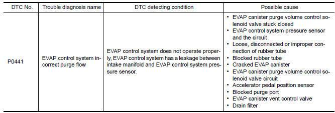
Nissan Maxima Service and Repair Manual: P0441 evap control system
DTC Logic
DTC DETECTION LOGIC
NOTE: If DTC P0441 is displayed with other DTC such as P2122, P2123, P2127, P2128 or P2138, first perform trouble diagnosis for other DTC.
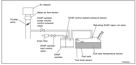
In this evaporative emission (EVAP) control system, purge flow occurs during non-closed throttle conditions.
Purge volume is related to air intake volume. Under normal purge conditions (non-closed throttle), the EVAP canister purge volume control solenoid valve is open to admit purge flow. Purge flow exposes the EVAP control system pressure sensor to intake manifold vacuum.
Under normal conditions (non-closed throttle), sensor output voltage indicates if pressure drop and purge flow are adequate. If not, a malfunction is determined.
DTC CONFIRMATION PROCEDURE
1.INSPECTION START
2.PRECONDITIONING
If DTC Confirmation Procedure has been previously conducted, always perform the following before conducting the next test.
- Turn ignition switch OFF and wait at least 10 seconds.
- Turn ignition switch ON.
- Turn ignition switch OFF and wait at least 10 seconds.
TESTING CONDITION: Always perform test at a temperature of 5C (41F) or more.
3.PERFORM DTC CONFIRMATION PROCEDURE-I
With CONSULT
- Start engine and warm it up to normal operating temperature.
- Turn ignition switch OFF and wait at least 10 seconds.
- Turn ignition switch ON.
- Turn ignition switch OFF and wait at least 10 seconds.
- Start engine and let it idle for at least 70 seconds.
- Select "PURG FLOW P0441" of "EVAPORATIVE SYSTEM" in "DTC WORK SUPPORT" mode with CONSULT.
- Touch "START".
4.PERFORM DTC CONFIRMATION PROCEDURE-II
When the following conditions are met, "TESTING" will be displayed on the CONSULT screen. Maintain the conditions continuously until "TESTING" changes to "COMPLETED". (It will take at least 35 seconds.)
CAUTION: Always drive vehicle at a safe speed.
If "TESTING" does not change for a long time, retry from step 2.
5.PERFORM DTC CONFIRMATION PROCEDURE-III
Touch "SELF-DIAG RESULTS".
6.PERFORM COMPONENT FUNCTION CHECK
Perform component function check. Refer to EC-311, "Component Function Check".
NOTE: Use component function check to check the overall monitoring function of the EVAP control system purge flow monitoring. During this check, a 1st trip DTC might not be confirmed.
Component Function Check
1.PERFORM COMPONENT FUNCTION CHECK
Without CONSULT
- Lift up drive wheels.
- Start engine (VDC switch OFF) and warm it up to normal operating temperature.
- Turn ignition switch OFF, wait at last 10 seconds.
- Turn ignition switch ON.
- Turn ignition switch OFF, wait at least 10 seconds.
- Start engine and wait at least 70 seconds.
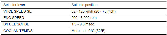
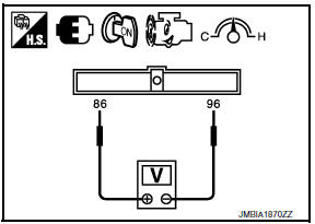
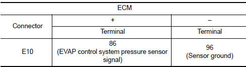
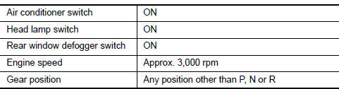
- Set voltmeter probes to ECM harness connector terminals under the following conditions.
- Check EVAP control system pressure sensor value at idle speed and note it.
- Establish and maintain the following conditions for at least 1 minute.
- Verify that EVAP control system pressure sensor value stays 0.1 V less than the value at idle speed (measured at step 6) for at least 1 second.
Diagnosis Procedure
1.CHECK EVAP CANISTER
- Turn ignition switch OFF.
- Check EVAP canister for cracks.
2.CHECK PURGE FLOW
With CONSULT
- Disconnect vacuum hose connected to EVAP canister purge volume control solenoid valve at EVAP service port and install vacuum gauge. For the location of EVAP service port, refer to EC-94, "System Diagram".
- Start engine and let it idle.
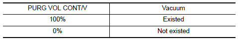
- Select "PURG VOL CONT/V" in "ACTIVE TEST" mode with CONSULT.
- Touch "Qd" and "Qu" on CONSULT screen to adjust "PURG VOL CONT/V" opening and check vacuum existence.
3.CHECK PURGE FLOW
Without CONSULT
- Start engine and warm it up to normal operating temperature.
- Stop engine.
- Disconnect vacuum hose connected to EVAP canister purge volume control solenoid valve at EVAP service port and install vacuum gauge. For the location of EVAP service port, refer to EC-94, "System Diagram".
- Start engine and let it idle.
Do not depress accelerator pedal even slightly.
- Check vacuum gauge indication before 60 seconds pass after starting engine.
Vacuum should not exist.
- Rev engine up to 2,000 rpm after 100 seconds pass after starting engine.
Vacuum should exist.
4.CHECK EVAP PURGE LINE
- Turn ignition switch OFF.
- Check EVAP purge line for improper connection or disconnection.
5.CHECK EVAP PURGE HOSE AND PURGE PORT
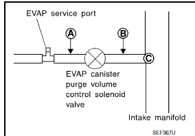
- Disconnect purge hoses connected to EVAP service port A and EVAP canister purge volume control solenoid valve B.
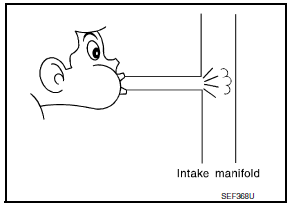
- Blow air into each hose and EVAP purge port C.
- Check that air flows freely.
6.CHECK EVAP CANISTER PURGE VOLUME CONTROL SOLENOID VALVE
With CONSULT
- Start engine.
- Perform "PURG VOL CONT/V" in "ACTIVE TEST" mode with CONSULT. Check that engine speed varies according to the valve opening.
7.CHECK EVAP CANISTER PURGE VOLUME CONTROL SOLENOID VALVE
8.CHECK EVAP CONTROL SYSTEM PRESSURE SENSOR CONNECTOR
- Disconnect EVAP control system pressure sensor harness connector.
- Check that water is not inside connectors.
9.CHECK EVAP CONTROL SYSTEM PRESSURE SENSOR FUNCTION
10.CHECK RUBBER TUBE FOR CLOGGING
- Disconnect rubber tube connected to EVAP canister vent control valve.
- Check the rubber tube for clogging.
11.CHECK DRAIN FILTER
12.CHECK EVAP CANISTER VENT CONTROL VALVE
13.CHECK EVAP PURGE LINE
Inspect EVAP purge line (pipe and rubber tube). Check for evidence of leakage.
14.CLEAN EVAP PURGE LINE
Clean EVAP purge line (pipe and rubber tube) using air blower.
15.CHECK INTERMITTENT INCIDENT
Component Inspection
DRAIN FILTER
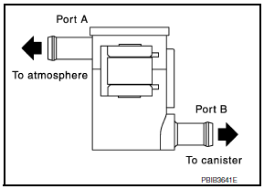
- Check visually for insect nests in the drain filter air inlet.
- Check visually for cracks or flaws in the appearance.
- Check visually for cracks or flaws in the hose.
- Blow air into port A and check that it flows freely out of port B.
- Block port B.
- Blow air into port A and check that there is no leakage.
- If NG, replace drain filter.
 P0420, P0430 three way catalyst function
DTC Logic
DTC DETECTION LOGIC
The ECM monitors the switching frequency ratio of air fuel ratio (A/F)
sensor 1 and heated oxygen sensor 2.
A three way catalyst (manifold) with high oxygen st ...
 P0442 evap control system
DTC Logic
DTC DETECTION LOGIC
This diagnosis detects leakage in the EVAP purge line using engine intake
manifold vacuum.
If pressure does not increase, the ECM will check for leakage in the lin ...
Other materials:
Wiring diagram
CHARGING SYSTEM
Wiring Diagram
...
Removal and installation
WHEEL HUB
Removal and Installation
Knuckle
Baffle plate
Wheel hub assembly
Brake rotor
Wheel nut
Anchor block
Wheel sensor
Parking brake cable
Refer to PB-6, "Exploded View".
Refer to BRC-103, "Removal and Installation
- Rear Wheel Sensor".
&nb ...
Fuel pressure
Inspection
FUEL PRESSURE RELEASE
With CONSULT
Turn ignition switch ON.
Perform "FUEL PRESSURE RELEASE" in "WORK SUPPORT" mode with
CONSULT.
Start engine.
After engine stalls, crank it two or three times to release all
fuel pressure.
Turn ignition switch OFF.
Without CONSULT
...
Nissan Maxima Owners Manual
- Illustrated table of contents
- Safety-Seats, seat belts and supplemental restraint system
- Instruments and controls
- Pre-driving checks and adjustments
- Monitor, climate, audio, phone and voice recognition systems
- Starting and driving
- In case of emergency
- Appearance and care
- Do-it-yourself
- Maintenance and schedules
- Technical and consumer information
Nissan Maxima Service and Repair Manual

0.0054