Nissan Maxima Owners Manual: Checking tire pressure
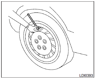
1. Remove the valve stem cap from the tire.
2. Press the pressure gauge squarely onto the valve stem. Do not press too hard or force the valve stem sideways, or air will escape. If the hissing sound of air escaping from the tire is heard while checking the pressure, reposition the gauge to eliminate this leakage.
3. Remove the gauge.
4. Read the tire pressure on the gauge stem and compare to the specification shown on the Tire and Loading Information label.
5. Add air to the tire as needed. If too much air is added, press the core of the valve stem briefly with the tip of the gauge stem to release pressure.
Recheck the pressure and add or release air as needed.
6. Install the valve stem cap.
7. Check the pressure of all other tires,
including the spare. 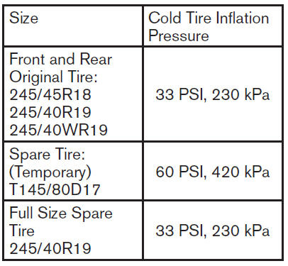
 Tire and loading information label
Seating capacity: The maximum number
of occupants that can be seated
in the vehicle.
Vehicle load limit: Refer to the loading
information in the "Technical and
consumer information" s ...
 Tire labeling
Example
Federal law requires tire manufacturers to
place standardized information on the
sidewall of all tires. This information identifies
and describes the fundamental
characteristics of the ...
Other materials:
Rear window defogger and door mirror defogger do not
operate
Diagnosis Procedure
1. CHECK REAR WINDOW DEFOGGER SWITCH
Check rear window defogger switch.
2. CHECK REAR WINDOW DEFOGGER RELAY
Check rear window defogger relay
3. CHECK FUSES
Check if any of the following fuses in fuse block (J/B) are blown.
4. CHECK REAR WINDOW DEFOGGER POWER SUPPLY CIR ...
Hood
Pull the hood lock release handle located
below the driver side instrument panel. The
hood will spring up slightly.
Push the lever at the front of the hood to the
side as illustrated with your fingertips and
raise the hood.
When closing the hood, lower it slowly and make
sure it l ...
U1310 AV control unit
Description
Part name
Description
AV CONTROL UNIT
It is the master unit of the MULTI AV system and it is connected
to each control unit by means of communication. It operates each
system according to communication signals from the AV contro ...
Nissan Maxima Owners Manual
- Illustrated table of contents
- Safety-Seats, seat belts and supplemental restraint system
- Instruments and controls
- Pre-driving checks and adjustments
- Monitor, climate, audio, phone and voice recognition systems
- Starting and driving
- In case of emergency
- Appearance and care
- Do-it-yourself
- Maintenance and schedules
- Technical and consumer information
Nissan Maxima Service and Repair Manual

0.0052