Nissan Maxima Service and Repair Manual: Front seat
DRIVER SIDE
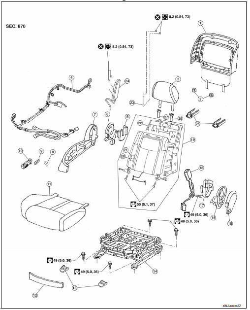
DRIVER SIDE : Exploded View
Driver Seat - Without Climate Controlled Seats
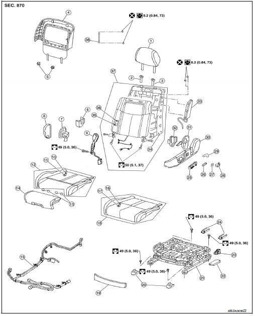
- Headrest
- Headrest holder (free)
- Headrest holder (locked)
- Seatback board
- Seatback board clip
- Seat cushion inner finisher inside (RH)
- Recline mechanism inner cover
- Seat cushion outer finisher (RH)
- Seat belt buckle
- Seat cushion trim
- Seat cushion pad
- Seat cushion assembly
- Thigh extension tether
- Thigh extension assembly
- Seat harness
- Seat cushion trim (w/o thigh extension)
- Seat cushion pad (w/o thigh extension)
- Seat cushion assembly (w/o thigh extension)
- Seat cushion front finisher
- Front slide cover
- Seat frame assembly
- Power seat control unit
- Actuator bracket
- Rear slide cover
- Power seat switch
- Seat slide and lifter switch knob
- Seat recline knob
- Lumbar support switch (if equipped)
- Lumbar lever (if equipped)
- Seat cushion outer finisher (LH)
- Recline device outer cover
- Seat cushion inner finisher (LH)
- Side air bag module
- Seatback frame
- Seatback pad
- Seatback trim
- Seatback assembly
- Chute rod
DRIVER SIDE : Disassembly and Assembly
SEAT ASSEMBLY WITH SIDE AIR BAG MODULE
WARNING:
Do not leave any objects (screwdriver, tools, etc.) on the seat during seatback repair. It can lead to personal injury if the side air bag should accidentally deploy.
CAUTION:
- Before servicing, turn the ignition switch OFF, disconnect both battery terminals and wait at least three minutes.
- Handle the side air bag module carefully. During disassembly, always hold the side air bag module, do not let it hang by the wire harness.
- Always place side air bag module with the stud bolt side facing downward.
- Always work from the side or back of the seatback assembly, do not work in front of the seat.
- Do not use air tools or electric tools when servicing the seat assembly.
- Replace the side air bag module if it has been dropped or sustained an impact.
- Do not insert any objects into the side air bag module.
- Do not disassemble the side air bag module.
- Do not expose the side air bag module to temperatures exceeding 93C (200F).
- Do not expose the side air bag module to any oil, grease or water.
- During disassembly, do not damage the trim cover, chutes, connectors, retainers, clips, module harness or the side air bag module.
NOTE:
- If the vehicle has been involved in a collision and the side air bag has deployed, the front seatback assembly must be replaced.
- For side air bag module removal and installation, refer to SR-21, "Removal and Installation".
Disassembly
- Remove the front seat assembly. Refer to SE-126, "Removal and Installation".
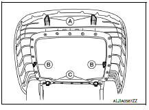
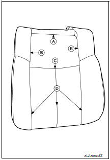
- Remove the seatback board as follows:
NOTE:
The seatback board is attached to the seat frame with the following:
- Two top hooks (A)
- Two side hooks (B)
- Two bottom retainers (C)
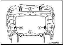
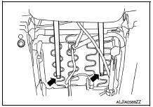
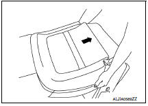
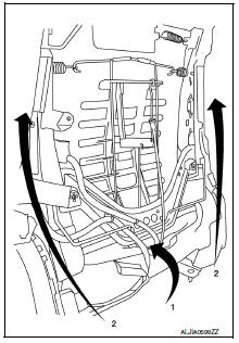
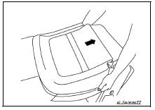
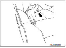
a. From the bottom of the seat, unhook the two seat skirt hooks as shown.
b. Carefully pull upward on the lower seatback board to release the two bottom retainers (C).
CAUTION:
Do not pull outward at two top hooks (A)
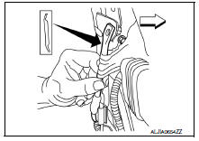
c. Hold the seatback board at the side hook locations (B) and push in the side hooks to release them from the seatback frame, then pull it rearward.
d. Carefully pull the seatback board downward to disengage the top hooks as shown.
CAUTION:
Use care not to break the seatback board hooks and retainers. Replace seatback board if any hooks or retainers are damaged.
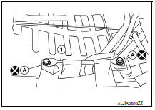
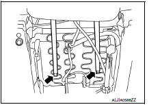
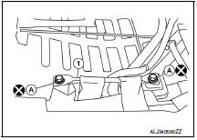
3. Remove and discard the two chute rod bolts (A), then remove the chute rod (1).
CAUTION:
Do not reuse the chute rod bolts.
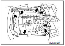
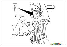
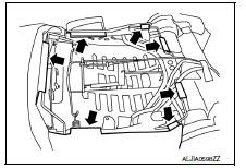
4. Release the seven seatback retainers from the seatback frame as shown.
5. Reach in from the bottom of the seatback to release the guide clips on the headrest holder. Squeeze the clips at the bottom and push upward to remove as shown.
6. Disconnect the harness connector for the seatback heater (if equipped).
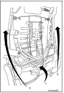
7. Push the seatback trim and seatback pad forward at the bottom (1), then holding the seatback assembly on both sides, lift upward (2). Remove the seatback trim and seatback pad as an assembly from the seatback frame.
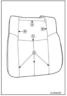
8. If required, separate the seatback trim from the seatback pad as follows:
NOTE:
The seatback trim is attached to the seatback pad with the following:
-
Five top hog rings (A)
-
Four side hog rings (B)
-
Three middle hog rings (C)
-
Three bottom velcro fasteners (D)
a. Pull the seatback trim cover from the seatback pad to detach the velcro fasteners. b. Position the seatback trim to access the middle hog rings. Remove the middle and side hog rings. c. Remove the top hog rings, then separate the seatback trim from the seatback pad.
Assembly
Assembly is in the reverse order of disassembly.
-
When installing the seatback trim, firmly push down while sliding your hand along the seams as shown (arrow) to ensure the velcro fasteners are fastened properly.
-
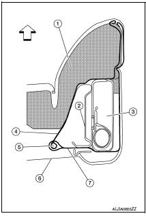
Make sure the chute rod is properly positioned and installed as shown.
 : Front
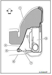
-
Make sure the side air bag outer chute (7) is pulled over the side air bag module (3) and the side air bag inner chute (4) is pulled around the frame (2). Make sure there are no wrinkles and the chutes are not folded, twisted or pinched
-
Seatback pad
-
Frame
-
Side air bag module
-
Inner side air bag chute
-
Chute rod
-
Seatback board
-
Outer chute
 : Front
CAUTION:
-
If a malfunction was detected by the air bag warning lamp, after repair or replacement of the malfunction parts, reset the memory using self-diagnosis or CONSULT.
-
After work is completed, check that no system malfunction is detected by air bag warning lamp.
-
Make sure side air bag module shell is closed at all tabs and cushion of module is not exposed. Do not reuse if the tab of shell is not secured.
-
Always install new side air bag module attaching nuts and side air bag chute rod bolts.
-
Always route side air bag module harness in original location. Replace any deformed or damaged clips with the same type and color. Always install clips in the original location on the harness.
-
Smooth out all wrinkles during assembly.
-
Inspect seatback pad, trim cover and trim cover chutes. Replace if damaged.
-
Replace any deformed or damaged parts.
-
Replace any deformed or damaged hog rings. Ensure any old hog ring pieces are removed from the seat
-
Use only one hog ring in each designated location.
-
Ensure hog rings are correctly fastened around both the seatback trim and seatback pad trim wires.
NOTE:
Use NISSAN standard hog rings and tools to assemble.
THIGH EXTENSION ASSEMBLY
Disassembly
-
Move the thigh extension assembly to the front most position and release the trim cover clips (A).
-
Remove the trim and pad (B).
3. Cut the thigh extension tethers and drill out the upper rivets (A) that connect the thigh extension tethers (B) to the thigh extension assembly (C).
4. Insert suitable tool into the thigh extension assembly top panel and release the clip (A). 5. Pull the thigh extension handle and remove the thigh extension assembly.
6. Drill out the lower rivets that connect the thigh extension tethers to the seat frame assembly.
Assembly
-
Replace the pad, trim and clips and to the thigh extension assembly.
-
Rivet the thigh extension tethers to the seat frame assembly mounting hole (A).
3. Align the thigh extension assembly on the top rail.
4. Lift the thigh extension handle and slide the thigh extension assembly onto the seat.
5. Rivet the thigh extension tethers to the thigh extension assembly mounting hole (A).
PASSENGER SIDE
PASSENGER SIDE : Exploded View
Passenger Seat
-
Seatback board
-
Seatback board clips
-
Headrest
-
Seat harness
-
Seat cushion inner finisher inside (RH)
-
Recline device inner cover
-
Seat cushion outer finisher (RH)
-
Seat recline knob
-
Seat slide and lifter switch knob
-
Power seat switch
-
Seat cushion assembly
-
Seat cushion front finisher
-
Front slide cover
-
Seat frame assembly
-
Seat cushion outer finisher (LH)
-
Recline mechanism inner cover
-
Seat cushion inner finisher inside (LH)
-
Seat belt buckle
-
Seatback assembly
-
Seatback pad
-
Seatback trim
-
Seatback frame
-
Chute rod
-
Side air bag module
-
Rear slide cover
-
Headrest holder (locked)
-
Headrest holder (free)
PASSENGER SIDE : Disassembly and Assembly
SEAT ASSEMBLY WITH SIDE AIR BAG MODULE
WARNING:
Do not leave any objects (screwdriver, tools, etc.) on the seat during seatback repair. It can lead to personal injury if the side air bag should accidentally deploy.
CAUTION:
-
Before servicing, turn the ignition switch OFF, disconnect both battery terminals and wait at least three minutes.
-
Handle the side air bag module carefully. During disassembly, always hold the side air bag module, do not let it hang by the wire harness.
-
Always place side air bag module with the stud bolt side facing downward.
-
Always work from the side or back of the seatback assembly, do not work in front of seat.
-
Do not use air tools or electric tools when servicing the seat assembly.
-
Replace the side air bag module if it has been dropped or sustained an impact.
-
Do not insert any objects into the side air bag module.
-
Do not disassemble the side air bag module.
-
Do not expose the side air bag module to temperatures exceeding 93C (200F).
-
Do not expose the side air bag module to any oil, grease or water.
-
During disassembly, do not damage the trim cover, chutes, connectors, retainers, clips, module harness or the side air bag module.
NOTE:
-
If the vehicle has been involved in a collision and the side air bag has deployed, the front seatback assembly must be replaced.
-
For side air bag module removal and installation, refer to SR-21, "Removal and Installation".
Disassembly
-
Remove the front seat assembly. Refer to SE-126, "Removal and Installation".
-
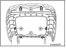
Remove the seatback board as follows:
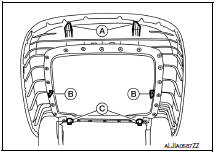
NOTE:
The seatback board is attached to the seat frame with the following:
-
Two top hooks (A)
-
Two side hooks (B)
-
Two bottom retainers (C)
a. From the bottom of the seat, unhook the two seat skirt hooks as shown.
b. Carefully pull upward on the lower seatback board to release the two bottom retainers (C).
CAUTION:
Do not pull outward at two top hooks (A)
c. Hold the seatback board at the side hook locations (B) and push in the side hooks to release them from the seatback frame, then pull it rearward.
d. Carefully pull the seatback board downward to disengage the top hooks as shown.
CAUTION:
Use care not to break the seatback board hooks and retainers. Replace seatback board if any hooks or retainers are damaged.
3. Remove and discard the two chute rod bolts (A), then remove the chute rod (1).
CAUTION:
Do not reuse the chute rod bolts.
4. Release the seven seatback retainers from the seatback frame as shown.
5. Reach in from the bottom of the seatback to release the guide clips on the headrest holder. Squeeze the clips at the bottom and push upward to remove as shown.
6. Disconnect the harness connector for the seatback heater (if equipped).
7. Push the seatback trim and seatback pad forward at the bottom (1), then holding the seatback assembly on both sides, lift upward (2). Remove the seatback trim
8. If required, separate the seatback trim from the seatback pad as follows:
NOTE:
The seatback trim is attached to the seatback pad with the following:
-
Five top hog rings (A)
-
Four side hog rings (B)
-
Three middle hog rings (C)
-
Three bottom velcro fasteners (D)
a. Pull the seatback trim cover from the seatback pad to detach the velcro fasteners.
b. Position the seatback trim to access the middle hog rings. Remove the middle and side hog rings.
c. Remove the top hog rings, then separate the seatback trim from the seatback pad.
Assembly
Assembly is in the reverse order of disassembly. During assembly, note the following.
-
When installing the seatback trim, firmly push down while sliding your hand along the seams as shown (arrow) to ensure the velcro fasteners are fastened properly.
-
Make sure the chute rod is properly positioned and installed as shown.
 : Front
-
Make sure the side air bag outer chute (7) is pulled over the side air bag module (3) and the side air bag inner chute (4) is pulled around the frame (2). Make sure there are no wrinkles and the chutes are not folded, twisted or pinched. (1) Seatback pad (5) Chute rod (6) Seatback board
 : Front
CAUTION:
-
If a malfunction was detected by the air bag warning lamp, after repair or replacement of the malfunction parts, reset the memory using self-diagnosis or CONSULT.
-
After work is completed, check that no system malfunction is detected by air bag warning lamp.
-
Make sure side air bag module shell is closed at all tabs and cushion of module is not exposed. Do not reuse if the tab of shell is not secured.
-
Always install new side air bag module attaching nuts and side air bag chute rod bolts.
-
Always route side air bag module harness in original location. Replace any deformed or damaged clips with the same type and color. Always install clips in the original location on the harness.
-
Smooth out all wrinkles during assembly.
-
Inspect seatback pad, trim cover and trim cover chutes. Replace if damaged.
-
Replace any deformed or damaged parts.
-
Replace any deformed or damaged hog rings. Ensure any old hog ring pieces are removed from seat.
-
Use only one hog ring in each designated location.
-
Ensure hog rings are correctly fastened around both the seatback trim and pad trim wires.
NOTE:
Use NISSAN standard hog rings and tools to assemble.

 Rear seat
Exploded View - Fixed Seatback
Headrest
Headrest holder (free)
Headrest holder (locked)
Bumper
Seatback assembly
&nbs ...
Other materials:
Navigation System
Turn-by-turn route guidance can be displayed on
the vehicle information display.
To view turn-by-turn route guidance on the vehicle
information display, use or
and
scroll to on the vehicle
information display
menu.
City view
City view shows representation of intersections
with ...
Power supply and ground circuit
BCM
BCM : Diagnosis Procedure
Regarding Wiring Diagram information, refer to BCS-67, "Wiring Diagram".
1. CHECK FUSE AND FUSIBLE LINK
Check if the following BCM fuses or fusible link are blown.
Is the fuse or fusible link blown?
2. CHECK POWER SUPPLY CIRCUIT
Turn ignition switch OFF.
...
P0130, P0150 A/F sensor 1
Description
The air fuel ratio (A/F) sensor 1 is a planar one-cell limit current sensor.
The sensor element of the A/F sensor 1 is composed an electrode
layer, which transports ions. It has a heater in the element.
The sensor is capable of precise measurement = 1, but also in the
lean ...
Nissan Maxima Owners Manual
- Illustrated table of contents
- Safety-Seats, seat belts and supplemental restraint system
- Instruments and controls
- Pre-driving checks and adjustments
- Monitor, climate, audio, phone and voice recognition systems
- Starting and driving
- In case of emergency
- Appearance and care
- Do-it-yourself
- Maintenance and schedules
- Technical and consumer information
Nissan Maxima Service and Repair Manual

0.0061