Nissan Maxima Service and Repair Manual: Rear seat
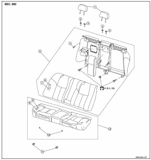
Exploded View - Fixed Seatback
-
Headrest
-
Headrest holder (free)
-
Headrest holder (locked)
-
Bumper
-
Seatback assembly
-
Seatback trim
-
Seatback pad
-
Seat cushion trim
-
Seat cushion pad
-
Seat cushion wire cover
-
Seat cushion lock
-
Seat cushion assembly
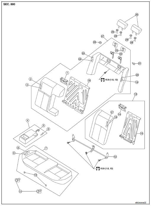
Exploded View - 60:40 Split Seatback
-
Seatback latch striker (RH)
-
Seatback trim (RH)
-
Seatback pad (RH)
-
Armrest assembly
-
Inner armrest bracket (RH)
-
Inner armrest bracket (LH)
-
Seat cushion assembly
-
Seat cushion trim
-
Seat cushion pad
-
Seat cushion wire cover
-
Seat cushion lock
-
Seatback hinge assembly
-
Seatback assembly (LH)
-
Seatback latch striker (LH)
-
Seatback frame (LH)
-
Seatback pad (LH)
-
Seatback trim (LH)
-
Seatback frame (RH)
-
Side bolster pad (LH)
-
Side bolster trim (LH)
-
Seat belt guide (LH)
-
Seatback latch assembly
-
Seatback latch cover
-
Side bolster pad (RH)
-
Side bolster trim (RH)
-
Seat belt guide (RH)
-
Seatback assembly (RH)
-
Headrest holder (locked)
-
Headrest holder (free)
-
Headrest
 Front seat
DRIVER SIDE
DRIVER SIDE : Exploded View
Driver Seat - Without Climate Controlled Seats
Headrest
Headrest holder (free)
Headrest holder (locked)
Seatback board
Seatback board clip
...

Other materials:
Bose speaker amp
Removal and Installation
Bose speaker amp.
Bose speaker amp. screws
REMOVAL
NOTE: If removing the BOSE speaker amp.
bracket, it is necessary to remove the parcel shelf finisher. The BOSE
speaker amp. can be removed without removing the BOSE speaker amp. bracket.
Disconnect the ...
Basic inspection
DIAGNOSIS AND REPAIR WORK FLOW
WITH COLOR DISPLAY
WITH COLOR DISPLAY : How to Perform Trouble Diagnosis For Quick And
Accurate Repair
WORK FLOW
1.LISTEN TO CUSTOMER COMPLAINT
Interview the customer to obtain as much information as possible about the
conditions and environment under which th ...
U1000 can comm circuit
Description
CAN (Controller Area Network) is a serial communication line for real time
applications. It is an on-vehicle multiplex
communication line with high data communication speed and excellent error
detection ability. Modern
vehicles are equipped with many electronic control units, an ...
Nissan Maxima Owners Manual
- Illustrated table of contents
- Safety-Seats, seat belts and supplemental restraint system
- Instruments and controls
- Pre-driving checks and adjustments
- Monitor, climate, audio, phone and voice recognition systems
- Starting and driving
- In case of emergency
- Appearance and care
- Do-it-yourself
- Maintenance and schedules
- Technical and consumer information
Nissan Maxima Service and Repair Manual

0.006