Nissan Maxima Service and Repair Manual: RGB synchronizing signal circuit
Description
Transmit the RGB synchronizing signal to the display unit so as to synchronize the RGB image displayed with AV control unit.
Diagnosis Procedure
1.CHECK CONTINUITY RGB SYNCHRONIZING SIGNAL CIRCUIT
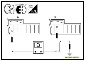
- Turn ignition switch OFF.
- Disconnect display unit connector M141 and AV control unit connector M154.
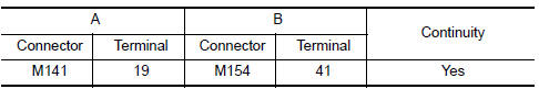
- Check continuity between display unit harness connector M141 (A) terminal 19 and AV control unit harness connector M154 (B) terminal 41.
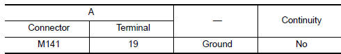
- Check continuity between display unit harness connector M141 (A) terminal 19 and ground.
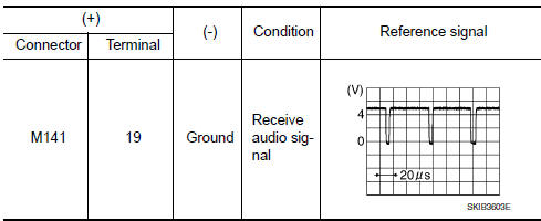
2.CHECK RGB SYNCHRONIZING SIGNAL
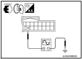
- Connect display unit connector M141 and AV control unit connector M154.
- Turn ignition switch ON.
- Check signal between display unit harness connector M141 terminal 19 and ground.
 RGB (B: blue) signal circuit
Description
Transmit the image displayed with AV control unit with RGB signal to the
display unit.
Diagnosis Procedure
1.CHECK CONTINUITY RGB (B: BLUE) SIGNAL CIRCUIT
Turn ignition switch ...
 RGB area (YS) signal circuit
Description
Transmits the display area of RGB image displayed by AV control unit with RGB
area (YS) signal to display
unit.
Diagnosis Procedure
1.CHECK CONTINUITY RGB AREA (YS) SIGNAL CIRCUIT
...
Other materials:
Adjust
For adjustable head restraint/headrest
Adjust the head restraint/headrest so the center
is level with the center of your ears. If your ear
position is still higher than the recommended
alignment, place the head restraint/headrest at
the highest position.
For non-adjustable head restraint/hea ...
U122A AV control unit
DTC Logic
Diagnosis Procedure
1.PERFORM THE SELF-DIAGNOSIS
When U122A is detected, write configuration data with "MULTI AV" of CONSULT.
U122E AV CONTROL UNIT
DTC Logic
DTC DETECTION LOGIC
...
Brake pedal
Exploded View
Clevis pin
Snap pin
Stop lamp switch
ASCD cancel switch
Clip
Brake pedal assembly
Brake pedal pad
NOTE:
The clevis pin must be installed from the RH side as shown.
Removal and Installation
REMOVAL
Remove instrument lower panel LH and lower knee protec ...
Nissan Maxima Owners Manual
- Illustrated table of contents
- Safety-Seats, seat belts and supplemental restraint system
- Instruments and controls
- Pre-driving checks and adjustments
- Monitor, climate, audio, phone and voice recognition systems
- Starting and driving
- In case of emergency
- Appearance and care
- Do-it-yourself
- Maintenance and schedules
- Technical and consumer information
Nissan Maxima Service and Repair Manual

0.0065