Nissan Maxima Service and Repair Manual: RGB area (YS) signal circuit
Description
Transmits the display area of RGB image displayed by AV control unit with RGB area (YS) signal to display unit.
Diagnosis Procedure
1.CHECK CONTINUITY RGB AREA (YS) SIGNAL CIRCUIT
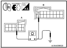
- Turn ignition switch OFF.
- Disconnect display unit connector M141 and AV control unit connector M154.
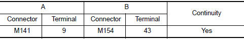
- Check continuity between display unit harness connector M141 (A) terminal 9 and AV control unit harness connector M154 (B) terminal 43.
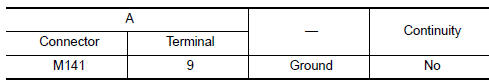
- Check continuity between display unit harness connector M141 (A) terminal 9 and ground.
2.CHECK RGB SYNCHRONIZING SIGNAL
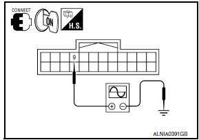
- Connect display unit connector M141 and AV control unit connector M154.
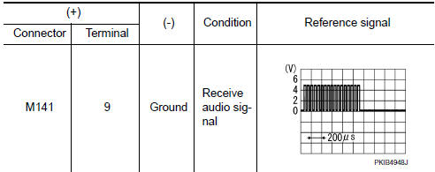
- Turn ignition switch ON.
- Check signal between display unit harness connector M141 terminal 9 and ground.
 RGB synchronizing signal circuit
Description
Transmit the RGB synchronizing signal to the display unit so as to
synchronize the RGB image displayed with
AV control unit.
Diagnosis Procedure
1.CHECK CONTINUITY RGB SYNCHRONIZING ...
 Horizontal synchronizing (HP) signal circuit
Description
In composite image (AUX image, camera image), transmit the vertical
synchronizing (VP) signal and horizontal
synchronizing (HP) signal from display unit to AV control unit so as to
...
Other materials:
Signal buffer system
System Diagram
System Description
IPDM E/R reads the status of the oil pressure switch and transmits the
oil pressure switch signal to BCM via
CAN communication.
IPDM E/R receives the rear window defogger status signal from BCM
via CAN communication and transmits
it to ECM via ...
Clearing the programmed information
The following procedure clears the programmed
information from both buttons. Individual buttons
cannot be cleared. However, individual buttons
can be reprogrammed. For additional information,
refer to "Reprogramming a single
HomeLink button" in this section.
To clear all programming:
1. Press ...
Tel antenna
Removal and Installation
REMOVAL
Disconnect the battery negative terminal. Refer to PG-67, "Removal
and Installation (Battery)".
Remove the rear parcel shelf finisher. Refer to INT-28, "Removal
and Installation".
Remove the Bluetooth antenna screw (A).
Detach the ...
Nissan Maxima Owners Manual
- Illustrated table of contents
- Safety-Seats, seat belts and supplemental restraint system
- Instruments and controls
- Pre-driving checks and adjustments
- Monitor, climate, audio, phone and voice recognition systems
- Starting and driving
- In case of emergency
- Appearance and care
- Do-it-yourself
- Maintenance and schedules
- Technical and consumer information
Nissan Maxima Service and Repair Manual

0.0069