Nissan Maxima Service and Repair Manual: RGB (B: blue) signal circuit
Description
Transmit the image displayed with AV control unit with RGB signal to the display unit.
Diagnosis Procedure
1.CHECK CONTINUITY RGB (B: BLUE) SIGNAL CIRCUIT
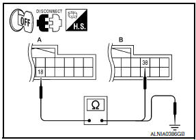
- Turn ignition switch OFF.
- Disconnect display unit connector M141 and AV control unit connector M154.
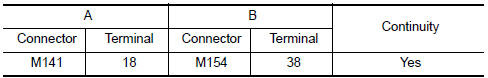
- Check continuity between display unit harness connector M141 (A) terminal 18 and AV control unit harness connector M154 (B) terminal 38.
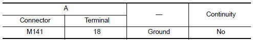
- Check continuity between display unit harness connector M141 (A) terminal 18 and ground.
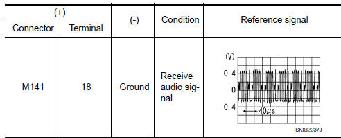
2.CHECK RGB (B: BLUE) SIGNAL
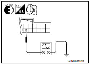
- Connect display unit connector M141 and AV control unit connector M154.
- Turn ignition switch ON.
- Check signal between display unit harness connector M141 terminal 18 and ground.
 RGB (G: green) signal circuit
Description
Transmit the image displayed with AV control unit with RGB signal to the
display unit.
Diagnosis Procedure
1.CHECK CONTINUITY RGB (G: GREEN) SIGNAL CIRCUIT
Turn ignition switc ...
 RGB synchronizing signal circuit
Description
Transmit the RGB synchronizing signal to the display unit so as to
synchronize the RGB image displayed with
AV control unit.
Diagnosis Procedure
1.CHECK CONTINUITY RGB SYNCHRONIZING ...
Other materials:
Headlights
Replacing the halogen headlight bulb
(if so equipped)
The headlight is a semi-sealed beam type which
uses a replaceable headlight (halogen) bulb.
They can be replaced from inside the engine
compartment without removing the headlight assembly.
If headlight bulb replacement is required, it i ...
Power window serial link
POWER WINDOW MAIN SWITCH
POWER WINDOW MAIN SWITCH : Description
Main power window and door lock/unlock switch, power window and door
lock/unlock switch RH and BCM
communicate via the power window serial link.
The keyless power window down signal is transmitted from BCM to
main power ...
Main line between dlc and hvac circuit
Diagnosis Procedure
1.CHECK HARNESS CONTINUITY (OPEN CIRCUIT)
Turn the ignition switch OFF.
Disconnect the battery cable from the negative
terminal.
Disconnect the following harness connectors.
ECM
A/C auto amp.
Check the continuity betw ...
Nissan Maxima Owners Manual
- Illustrated table of contents
- Safety-Seats, seat belts and supplemental restraint system
- Instruments and controls
- Pre-driving checks and adjustments
- Monitor, climate, audio, phone and voice recognition systems
- Starting and driving
- In case of emergency
- Appearance and care
- Do-it-yourself
- Maintenance and schedules
- Technical and consumer information
Nissan Maxima Service and Repair Manual

0.0076