Nissan Maxima Service and Repair Manual: Front fog lamp
Exploded View
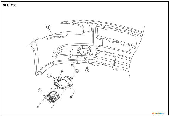
- Front bumper fascia
- Front fog lamp
- Front fog lamp bracket
- Clip
- Spring nuts
Removal and Installation
FRONT FOG LAMP
Removal
- Remove the front bumper fascia. Refer to EXT-16, "Removal and Installation".
- Disconnect the harness connector from the fog lamp.
- Remove the front fog lamp bolts.
- Remove the front fog lamp.
Installation
Installation is in the reverse order of removal.
NOTE: After installation, perform front fog lamp aiming adjustment. Refer to EXL-317, "Aiming Adjustment Procedure".
FRONT FOG LAMP BULB
Removal
WARNING: Do not touch bulb with your hand while it is on or right after being turned off, a burn injury may result.
CAUTION:
- Do not touch bulb glass with your hand or keep other grease and oily substances away from bulb glass.
- Do not leave bulb out of lamp reflector for a long time because dust, moisture smoke, etc. may affect the performance of lamp. When replacing bulb, be sure to replace it with new one.
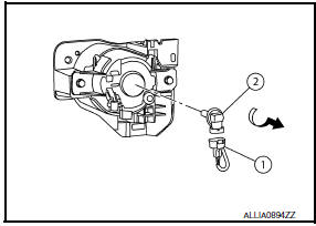
- Remove the front fender protector. Refer to EXT-24, "Removal and Installation".
- Disconnect the harness connector (1) from the front fog lamp.
- Rotate the bulb (2) counterclockwise and unlock it.
Installation
Installation is in the reverse order of removal.
 Front combination lamp
Exploded View
Front combination lam
Removal and Installation
FRONT COMBINATION LAMP
Removal
Remove the front bumper fascia. Refer to EXT-16, "Removal and
Installation".
Remove the ...
 Optical sensor
Exploded View
Optical sensor
LH front tweeter speaker grille
Optical sensor harness connector
LH front tweeter speaker
Instrument panel
Removal and Installation
CAUTION: Whenever ...
Other materials:
Door switch
Description
Detects front door open/close condition.
Component Function Check
1.CHECK FUNCTION
With CONSULT
Check front door switches DOOR SW-DR and DOOR SW-AS in Data Monitor mode with
CONSULT.
Diagnosis Procedure
1.CHECK FRONT DOOR SWITCH INPUT SIGNAL
Turn ignition switch OFF.
...
AV control unit
Reference Value
VALUES ON THE DIAGNOSIS TOOL
CONSULT data monitor item
TERMINAL LAYOUT
PHYSICAL VALUES
DTC Index
SELF-DIAGNOSIS RESULTS DISPLAY ITEM
...
Audio antenna
Location of Antenna
AV control unit
AV control unit antenna feeder
In-line connectors M103, M501
Antenna amp.
Window antenna
Satellite radio antenna feeder
Satellite radio antenna
Window Antenna Repair
ELEMENT CHECK
Attach probe circuit tester (ohm setting) to antenna ...
Nissan Maxima Owners Manual
- Illustrated table of contents
- Safety-Seats, seat belts and supplemental restraint system
- Instruments and controls
- Pre-driving checks and adjustments
- Monitor, climate, audio, phone and voice recognition systems
- Starting and driving
- In case of emergency
- Appearance and care
- Do-it-yourself
- Maintenance and schedules
- Technical and consumer information
Nissan Maxima Service and Repair Manual

0.0076