Nissan Maxima Service and Repair Manual: Front combination lamp
Exploded View
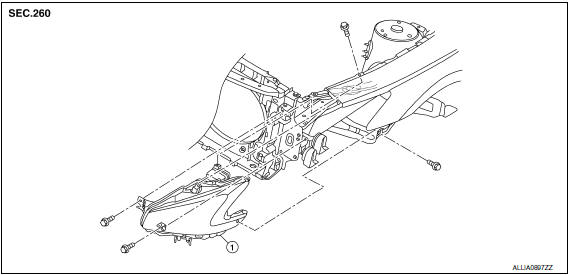
- Front combination lam
Removal and Installation
FRONT COMBINATION LAMP
Removal
- Remove the front bumper fascia. Refer to EXT-16, "Removal and Installation".
- Remove the front combination lamp bolts.
- Remove the harness clips from the front combination lamp assembly.
- Pull out the front combination lamp toward the front of vehicle.
- Disconnect the harness connectors from the front combination lamp and remove.
Installation
Installation is in the reverse order of removal.
NOTE: After installation, perform headlamp aiming adjustment. Refer to EXL-315, "Aiming Adjustment Procedure".
HALOGEN BULB (LOW BEAM)
Removal
WARNING: Do not touch bulb with your hand while it is on or right after being turned off, a burn injury may result.
CAUTION:
- After installing the bulb, install the plastic cover and the bulb socket securely for watertightness.
- Do not touch bulb glass with your hand or keep other grease and oily substances away from bulb glass.
- Do not leave bulb out of lamp reflector for a long time because dust, moisture smoke, etc. may affect the performance of lamp. When replacing bulb, be sure to replace it with new one.
- Remove the front combination lamp. Refer to EXL-318, "Removal and Installation".
- Rotate the bulb socket counterclockwise and unlock from the front combination lamp.
- Remove the bulb from the bulb socket
Installation is in the reverse order of removal.
HALOGEN BULB (HIGH BEAM)
Removal
- Remove the front combination lamp. Refer to EXL-318, "Removal and Installation".
- Rotate the bulb socket counterclockwise and unlock from the front combination lamp.
- Remove the bulb from the bulb socket.
Installation
Installation is in the reverse order of removal.
FRONT TURN SIGNAL LAMP BULB
Removal
- Remove the front combination lamp. Refer to EXL-318, "Removal and Installation".
- Rotate the bulb socket counterclockwise and unlock from the front combination lamp.
- Remove the bulb from the bulb socket.
Installation
Installation is in the reverse order of removal.
FRONT SIDE MARKER LAMP BULB
Removal
- Remove the front combination lamp. Refer to EXL-318, "Removal and Installation".
- Rotate the bulb socket counterclockwise and unlock from the front combination lamp.
- Remove the bulb from the bulb socket.
Installation
Installation is in the reverse order of removal.

 Front fog lamp
Exploded View
Front bumper fascia
Front fog lamp
Front fog lamp bracket
Clip
Spring nuts
Removal and Installation
FRONT FOG LAMP
Removal
Remove the front bumper fascia. ...
Other materials:
Removal and installation
EXHAUST SYSTEM
Exploded View
Front exhaust tube
Ring gasket
Front exhaust tube stay
Front exhaust tube bracket
Gasket
Center exhaust tube rubber hanger
Center exhaust tube
Center exhaust tube hanger
Rear muffler bracket (RH)
Rear muffler (RH)
Rear muffler bracket (LH) ...
P014C, P014D, P014E, P014F, P015A, P015B, P015C, P015D A/F sensor
1
Description
The air fuel ratio (A/F) sensor 1 is a planar one-cell limit current sensor.
The sensor element of the A/F sensor 1 is composed an electrode
layer, which transports ions. It has a heater in the element.
The sensor is capable of precise measurement = 1, but also in the
lean ...
Entry/exit function
This system is designed so that the driver's seat
and automatic operation steering column will automatically
move when the shift lever is in the P
(Park) position. This allows the driver to get into
and out of the driver's seat more easily.
The driver's seat will slide backward and the
steer ...
Nissan Maxima Owners Manual
- Illustrated table of contents
- Safety-Seats, seat belts and supplemental restraint system
- Instruments and controls
- Pre-driving checks and adjustments
- Monitor, climate, audio, phone and voice recognition systems
- Starting and driving
- In case of emergency
- Appearance and care
- Do-it-yourself
- Maintenance and schedules
- Technical and consumer information
Nissan Maxima Service and Repair Manual

0.0071