Nissan Maxima Service and Repair Manual: IPDM-E branch line circuit
Diagnosis Procedure
1.CHECK CONNECTOR
- Turn the ignition switch OFF.
- Disconnect the battery cable from the negative terminal.
- Check the terminals and connectors of the IPDM E/R for damage, bend and loose connection (unit side and connector side).
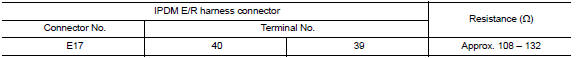
2.CHECK HARNESS FOR OPEN CIRCUIT
- Disconnect the connector of IPDM E/R.
- Check the resistance between the IPDM E/R harness connector terminals.
3.CHECK POWER SUPPLY AND GROUND CIRCUIT
Check the power supply and the ground circuit of the IPDM E/R. Refer to PCS-18, "Diagnosis Procedure".
 TCM branch line circuit
Diagnosis Procedure
1.CHECK CONNECTOR
Turn the ignition switch OFF.
Disconnect the battery cable from the negative terminal.
Check the following terminals and connectors for damage, bend and ...
 CAN communication circuit
Diagnosis Procedure
1.CONNECTOR INSPECTION
Turn the ignition switch OFF.
Disconnect the battery cable from the negative terminal.
Disconnect all the unit connectors on CAN communication syste ...
Other materials:
Communication signal circuit
SATELLITE RADIO TUNER
SATELLITE RADIO TUNER : Description
Communication signals are exchanged between the AV control unit and satellite
radio tuner using the communication circuits.
SATELLITE RADIO TUNER : Diagnosis Procedure
1.CHECK HARNESS - 1
Turn ignition switch OFF.
Disconnect sat ...
VDC/TCS/ABS
Symptom Table
If ABS warning lamp, SLIP indicator lamp turn ON, perform self-diagnosis.
NOTE:
1: The ABS does not operate when the speed is 10 km/h (6 MPH)
or less.
2: Under the following conditions, ABS is activated and
vibration is felt when brake pedal is lightly dep ...
Basic inspection
DIAGNOSIS AND REPAIR WORKFLOW
Work Flow (With EXP-800 NI or GR8-1200 NI)
CHARGING SYSTEM DIAGNOSIS WITH EXP-800 NI OR GR8-1200 NI
To test the charging system, use the following special service tools:
EXP-800 NI Battery and electrical diagnostic analyzer
GR8-1200 NI Multitasking battery and ...
Nissan Maxima Owners Manual
- Illustrated table of contents
- Safety-Seats, seat belts and supplemental restraint system
- Instruments and controls
- Pre-driving checks and adjustments
- Monitor, climate, audio, phone and voice recognition systems
- Starting and driving
- In case of emergency
- Appearance and care
- Do-it-yourself
- Maintenance and schedules
- Technical and consumer information
Nissan Maxima Service and Repair Manual

0.0074