Nissan Maxima Service and Repair Manual: System description
ENGINE CONTROL SYSTEM
System Diagram
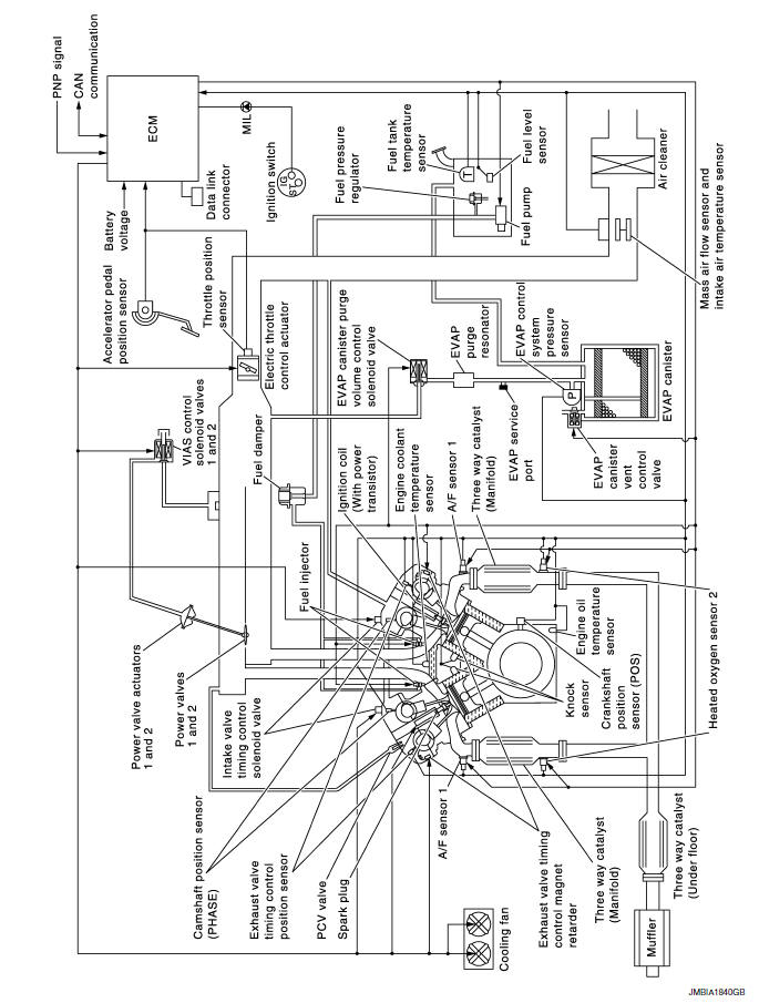
System Description
ECM performs various controls such as fuel injection control and ignition timing control.
Component Parts Location
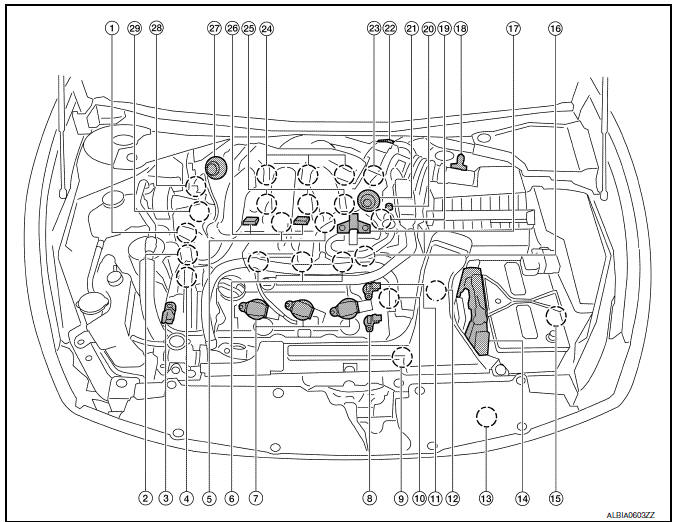
- Intake valve timing control solenoid valve (bank 1)
- Electronic controlled engine mount control solenoid valve
- Exhaust valve timing control magnet retarder (bank 2)
- Intake valve timing control solenoid valve (bank 2)
- Knock sensor (bank 1 and 2)
- Fuel injector (bank 2)
- Ignition coil (with power transistor) and spark plug (bank 2)
- Exhaust valve timing control position sensor (bank 2)
- Crankshaft position sensor (POS)
- Engine coolant temperature sensor 11. Camshaft position sensor (PHASE) (bank 2)
- Transmission range switch
- Refrigerant pressure sensor
- ECM
- Battery current sensor
- Condenser-2
- EVAP canister purge volume control solenoid valve
- Mass air flow sensor (with intake air temperature sensor)
- Camshaft position sensor (PHASE) (bank 1)
- EVAP service port
- Power valve actuator 2
- Electric throttle control actuator
- Exhaust valve timing control position sensor (bank 1)
- Ignition coil (with power transistor) and spark plug (bank 1)
- Fuel injector (bank 1)
- VIAS control solenoid valve 1 and 2
- Power valve actuator 1
- Exhaust valve timing control magnet retarder (bank 1)
- Power steering pressure sensor
- Mas air flow sensor (with intake air temperature sensor)
- Air cleaner case
- Engine coolant temperature sensor (view with engine cover removed)
- EVAP canister purge volume control solenoid valve (view with engine cover removed)
- Power valve actuator 1 (view with engine cover removed)
- VIAS control solenoid valve 1
- VIAS control solenoid valve 2
- Power valve actuator 2
- Power steering pressure sensor
- Tie rod (RH)
- Camshaft position sensor (PHASE) (bank 1) (view with air cleaner case removed)
- Exhaust valve timing control position sensor (bank 1)
- Camshaft position sensor (PHASE) (bank 2) (view with air cleaner case removed)
- Exhaust valve timing control position sensor (bank 2)
- . Engine oil temperature sensor
 : Vehicle front
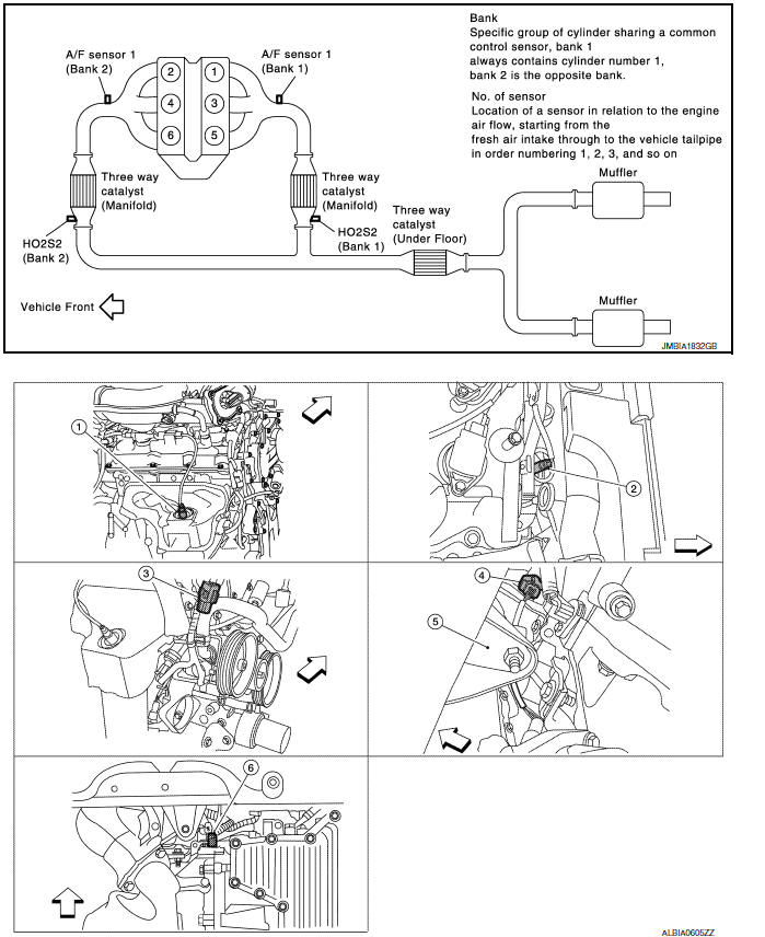
- A/F sensor 1 (bank 1) (view with engine removed)
- A/F sensor 1 (bank 2)
- HO2S2 (bank 1) harness connector (view with engine removed)
- HO2S2 (bank 2) harness connector
- Front engine mount
- Crankshaft position sensor (POS)
 : Vehicle front
- Electronic controlled engine mount control solenoid valve (view with engine cover removed)
- EVAP control system pressure sensor (view with rear suspension member removed)
- EVAP canister vent control valve
- EVAP canister
- Fuel injector harness connector (view with intake manifold collector removed)
- Exhaust valve timing control magnet retarder (bank 1) (view with engine removed)
- Intake valve timing control solenoid valve (bank 1)
- Intake valve timing control solenoid valve (bank 2)
- Exhaust valve timing control magnet
retarder (bank 2)
 : Vehicle front
- Knock sensor (bank 2) (view with intake manifold removed)
- Knock sensor (bank 1)
- Transmission range switch (view with CVT removed)
- Battery
- IPDM E/R
- ECM
- Refrigerant pressure sensor (view with front grille removed)
- Accelerator pedal position sensor
 : Vehicle front
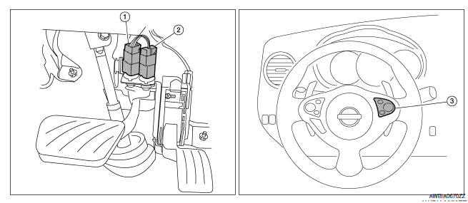
- Stop lamp switch
- ASCD brake switch
- ASCD steering switch
Component Description
Component Reference
- A/F sensor 1 EC-218, "Description"
- A/F sensor 1 heater EC-170, "Description"
- Accelerator pedal position sensor EC-467, "Description"
- ASCD brake switch EC-429, "Description"
- ASCD steering switch EC-426, "Description"
- Battery current sensor EC-414, "Description"
- Camshaft position sensor (PHASE) EC-300, "Description"
- Crankshaft position sensor (POS) EC-296, "Description"
- Cooling fan motor EC-486, "Description"
- Electric throttle control actuator EC-465, "Description"
- Electronic controlled engine mount EC-493, "Description"
- Engine coolant temperature sensor EC-201, "Description"
- Engine oil temperature sensor EC-277, "Description"
- EVAP canister purge volume control solenoid valve EC-323, "Description"
- EVAP canister vent control valve EC-333, "Description"
- EVAP control system pressure sensor EC-343, "Description"
- Fuel injector EC-496, "Description"
- Fuel level sensor EC-372, "Description"
- Fuel pump EC-499, "Description"
- Fuel tank temperature sensor EC-269, "Description"
- Heated oxygen sensor 2 EC-230, "Description"
- Heated oxygen sensor 2 heater EC-173, "Description"
- Ignition coil with power transistor EC-502, "Description"
- Intake air temperature sensor EC-198, "Description"
- Intake valve timing control solenoid valve EC-177, "Description"
- Knock sensor EC-293, "Description"
- Mass air flow sensor
- PCV valve EC-514, "Description"
- Power steering pressure sensor EC-386, "Description"
- Power valves 1 and 2 EC-518, "Description"
- Refrigerant pressure sensor EC-515, "Description"
- Stop lamp switch EC-448, "Description"
- TCM EC-397, "Description"
- Throttle control motor EC-462, "Description"
- Throttle control motor relay EC-456, "Description"
- Throttle position sensor EC-207, "Description"
- VIAS control solenoid valve 1 EC-442, "Description"
- VIAS control solenoid valve 2
- Multiport fuel injection system
- Electric ignition system
- Air conditioning cut control
- Automatic speed control device (ASCD)
- Can communication
- Cooling fan control
- Electronic controlled engine mount
- Evaporative emission system
- Exhaust valve timing control
- Intake valve timing control
- Variable induction air system
- Fuel filler cap warning system
- On board diagnostic (OBD) system
- Diagnosis system (ECM)
 How to erase permanent DTC
Description
OUTLINE
When a DTC is stored in ECM
When a DTC is stored in ECM and MIL is ON, a permanent DTC is erased with MIL
shutoff if the same malfunction
is not detected after performing th ...
 Multiport fuel injection system
System Diagram
System Description
INPUT/OUTPUT SIGNAL CHART
*1: This sensor is not used to control the engine system under normal
conditions.
*2: This signal is sent to the ECM via the ...
Other materials:
AV branch line circuit
Diagnosis Procedure
1.CHECK CONNECTOR
Turn the ignition switch OFF.
Disconnect the battery cable from the negative terminal.
Check the terminals and connectors of the AV control unit for
damage, bend and loose connection (unit
side and connector side).
2.CHECK HARNESS FOR OPEN CIRC ...
P1078, P1084 EVT control position sensor
Description
Exhaust valve timing control position sensor detects the concave
groove of the exhaust camshaft rear end.
This sensor signal is used for sensing a position of the exhaust camshaft.
This sensor uses a Hall IC.
Based on the position of the exhaust camshaft, ECM controls
e ...
Warning function symptoms
Symptom Table
WARNING FUNCTION MALFUNCTION
NOTE:
Before performing the diagnosis in the following table, check
"WORK FLOW". Refer to DLK-9, "Work Flow".
Check that vehicle is under the condition shown in "Conditions
of vehicle" before starting diagnosis, and
check each sy ...
Nissan Maxima Owners Manual
- Illustrated table of contents
- Safety-Seats, seat belts and supplemental restraint system
- Instruments and controls
- Pre-driving checks and adjustments
- Monitor, climate, audio, phone and voice recognition systems
- Starting and driving
- In case of emergency
- Appearance and care
- Do-it-yourself
- Maintenance and schedules
- Technical and consumer information
Nissan Maxima Service and Repair Manual

0.0076