Nissan Maxima Service and Repair Manual: Cooling fan control
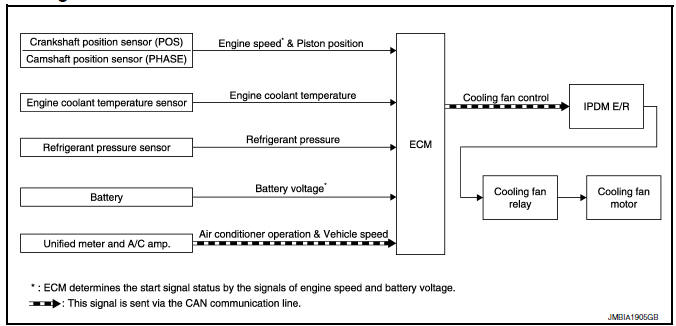
System Diagram
System Description
INPUT/OUTPUT SIGNAL CHART
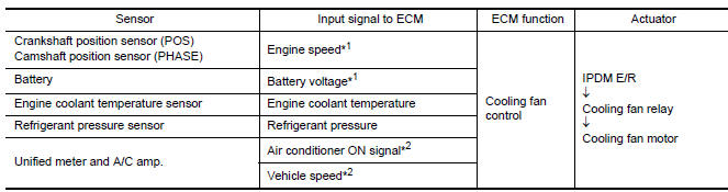
*1: The ECM determines the start signal status by the signals of engine speed
and battery voltage.
*2: This signal is sent to ECM via the CAN communication line.
SYSTEM DESCRIPTION
The ECM controls the cooling fan corresponding to the vehicle speed, engine coolant temperature, refrigerant pressure, and air conditioner ON signal. The control system has 4-step control [HIGH/MIDDLE/LOW/OFF].
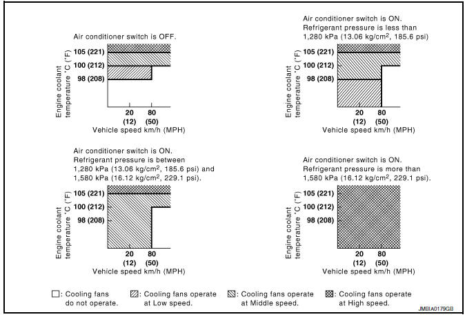
Cooling Fan Operation
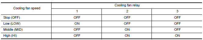
Cooling Fan Relay Operation
The ECM controls cooling fan relays in the IPDM E/R via the CAN communication line.
Component Parts Location
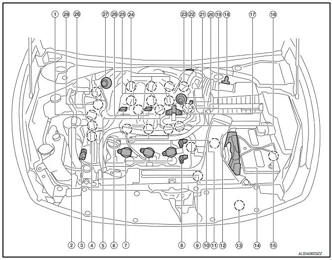
- Intake valve timing control solenoid valve (bank 1)
- Electronic controlled engine mount control solenoid valve
- Exhaust valve timing control magnet retarder (bank 2)
- Intake valve timing control solenoid valve (bank 2)
- Knock sensor (bank 1 and 2)
- Fuel injector (bank 2)
- Ignition coil (with power transistor) and spark plug (bank 2)
- Exhaust valve timing control position sensor (bank 2)
- Crankshaft position sensor (POS)
- Engine coolant temperature sensor
- Camshaft position sensor (PHASE) (bank 2)
- Transmission range switch
- Refrigerant pressure sensor
- ECM
- Battery current sensor
- Condenser-2
- EVAP canister purge volume control solenoid valve
- Mass air flow sensor (with intake air temperature sensor)
- Camshaft position sensor (PHASE) (bank 1)
- EVAP service port
- Power valve actuator 2
- Electric throttle control actuator
- Exhaust valve timing control position sensor (bank 1)
- Ignition coil (with power transistor) and spark plug (bank 1)
- Fuel injector (bank 1)
- VIAS control solenoid valve 1 and 2
- Power valve actuator 1
- Exhaust valve timing control magnet retarder (bank 1)
- Power steering pressure sensor
- Mas air flow sensor (with intake air temperature sensor)
- Air cleaner case
- Engine coolant temperature sensor (view with engine cover removed)
- EVAP canister purge volume control solenoid valve (view with engine cover removed)
- Power valve actuator 1 (view with engine cover removed)
- VIAS control solenoid valve 1
- VIAS control solenoid valve 2
- Power valve actuator 2
- Power steering pressure sensor
- Tie rod (RH)
- Camshaft position sensor (PHASE) (bank 1) (view with air cleaner case removed)
- Exhaust valve timing control position sensor (bank 1)
- Camshaft position sensor (PHASE) (bank 2) (view with air cleaner case removed)
- Exhaust valve timing control position sensor (bank 2)
- Engine oil temperature sensor
 : Vehicle front
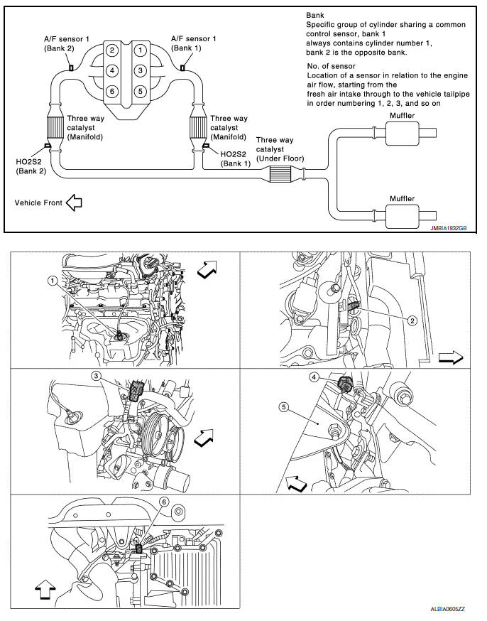
- A/F sensor 1 (bank 1) (view with engine removed)
- A/F sensor 1 (bank 2)
- HO2S2 (bank 1) harness connector (view with engine removed)
- HO2S2 (bank 2) harness connector
- Front engine mount
- Crankshaft position sensor (POS)
 : Vehicle front
- Electronic controlled engine mount control solenoid valve (view with engine cover removed)
- EVAP control system pressure sensor (view with rear suspension member removed)
- EVAP canister vent control valve
- EVAP canister
- Fuel injector harness connector (view with intake manifold collector removed)
- Exhaust valve timing control magnet retarder (bank 1) (view with engine removed)
- Intake valve timing control solenoid valve (bank 1)
- Intake valve timing control solenoid valve (bank 2)
- Exhaust valve timing control magnet
retarder (bank 2)
 : Vehicle front
- Knock sensor (bank 2) (view with intake manifold removed)
- Knock sensor (bank 1)
- Transmission range switch (view with CVT removed)
- Battery
- IPDM E/R
- ECM
- Refrigerant pressure sensor (view with front grille removed)
- Accelerator pedal position sensor
 : Vehicle front
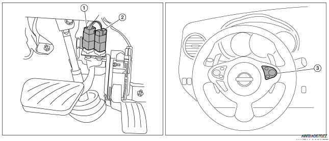
- Stop lamp switch
- ASCD brake switch
- ASCD steering switch
Component Description
Component Reference
- Camshaft position sensor (PHASE) EC-300, "Description"
- Crankshaft position sensor (POS) EC-296, "Description"
- Cooling fan motor EC-486, "Description"
- Engine coolant temperature sensor EC-201, "Description"
- Refrigerant pressure sensor
 Can communication
System Description
CAN (Controller Area Network) is a serial communication line for real time
application. It is an on-vehicle multiplex
communication line with high data communication speed and ...
 Electronic controlled engine mount
System Diagram
System Description
INPUT/OUTPUT SIGNAL CHART
*: This signal is sent to the ECM via the CAN communication line.
SYSTEM DESCRIPTION
The ECM controls the engine mount operatio ...
Other materials:
Hazard warning flasher switch
Push the switch on to warn other drivers when
you must stop or park under emergency conditions.
All turn signal lights flash.
WARNING
If stopping for an emergency, be sure to
move the vehicle well off the road.
Do not use the hazard warning flashers
while moving on the highway unl ...
Sunload sensor
Removal and Installation
REMOVAL
Remove the front LH speaker grille from the instrument panel.
Refer to IP-10, "Exploded View".
Disconnect the harness connector from the sunload sensor.
Release the sunload sensor tabs and remove the sunload sensor
(1) from the front LH speake ...
Wheel sensors
Exploded View - Front Wheel Sensor
Front wheel sensor
Color line (slant line)
Front wheel sensor harness connector
Front
Removal and Installation - Front Wheel Sensor
CAUTION:
Be careful not to damage wheel sensor edge and sensor rotor
teeth.
When pul ...
Nissan Maxima Owners Manual
- Illustrated table of contents
- Safety-Seats, seat belts and supplemental restraint system
- Instruments and controls
- Pre-driving checks and adjustments
- Monitor, climate, audio, phone and voice recognition systems
- Starting and driving
- In case of emergency
- Appearance and care
- Do-it-yourself
- Maintenance and schedules
- Technical and consumer information
Nissan Maxima Service and Repair Manual

0.0088