Nissan Maxima Service and Repair Manual: The oil pressure warning lamp does not turn off
Description
The oil pressure warning lamp remains illuminated while the engine is running (normal oil pressure).
Diagnosis Procedure
Regarding Wiring Diagram information, refer to MWI-87, "Wiring Diagram".
1.CHECK OIL PRESSURE WARNING LAMP
Perform IPDM E/R auto active test. Refer to PCS-11, "Diagnosis Description".
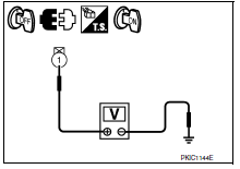
2.CHECK IPDM E/R OUTPUT VOLTAGE
-
Turn ignition switch OFF.
-
Disconnect the oil pressure switch connector.
-
Turn ignition switch ON.
-
Check voltage between the oil pressure switch harness connector F41 terminal 1 and ground.

3.CHECK OIL PRESSURE SWITCH
Perform a unit check for the oil pressure switch. Refer to MWI-42, "Component Inspection".
4.CHECK OIL PRESSURE SWITCH SIGNAL CIRCUIT
Check the oil pressure switch signal circuit. Refer to MWI-42, "Diagnosis Procedure".
 The oil pressure warning lamp does not turn on
Description
The oil pressure warning lamp stays off when the ignition
switch is turned ON.
Diagnosis Procedure
1.CHECK OIL PRESSURE WARNING LAMP
Perform IPDM E/R auto active test. Refer to PCS-1 ...
 The parking brake release warning continues displaying, or does not display
Description
The parking brake warning is displayed while
driving the vehicle even though the parking brake is released.
The parking brake warning is not displayed even
...
Other materials:
U1207 AV control unit
DTC Logic
Diagnosis Procedure
1.PERFORM THE SELF-DIAGNOSIS
Delete the "self-diagnosis" results of "MULTI AV". Turn ignition
switch OFF.
Turn ignition switch ON. Perform the self-diagnosis again.
Check that the DTC is detected again.
U1216 AV CONTROL UNIT
DTC Logic
U1217 AV ...
Front door speaker
Description
The AV control unit sends audio signals to the BOSE speaker amp. The BOSE
speaker amp. amplifies the
audio signals before sending them to the front door speakers using the audio
signal circuits.
Diagnosis Procedure
1.CONNECTOR CHECK
Check the AV control unit, BOSE speaker amp. ...
Driver air bag module
Exploded View
Driver air bag module
Side lid
Driver air bag module harness connectors
Steering wheel switch assembly connector
Driver air bag module bolt
Removal and Installation
CAUTION:
Before servicing, turn ignition switch OFF, disconnect both
battery terminals and wai ...
Nissan Maxima Owners Manual
- Illustrated table of contents
- Safety-Seats, seat belts and supplemental restraint system
- Instruments and controls
- Pre-driving checks and adjustments
- Monitor, climate, audio, phone and voice recognition systems
- Starting and driving
- In case of emergency
- Appearance and care
- Do-it-yourself
- Maintenance and schedules
- Technical and consumer information
Nissan Maxima Service and Repair Manual
0.0065
