Nissan Maxima Service and Repair Manual: Exhaust valve timing control
System Diagram
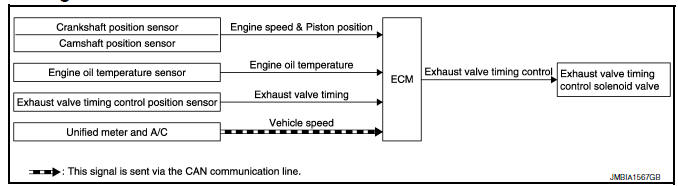
System Description
INPUT/OUTPUT SIGNAL CHART
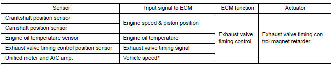
*: This signal is sent to the ECM via the CAN Communication line.
SYSTEM DESCRIPTION
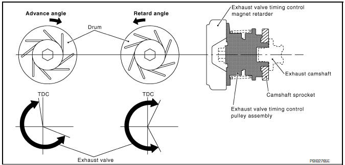
This mechanism magnetically controls cam phases continuously with the fixed operating angle of the exhaust valve.
The ECM receives signals such as crankshaft position, camshaft position, engine speed, and engine oil temperature.
Then, the ECM sends ON/OFF pulse duty signals to the exhaust valve timing control magnet retarder depending on driving status. This makes it possible to control the shut/open timing of the exhaust valve to increase engine torque and output in a range of high engine speed.
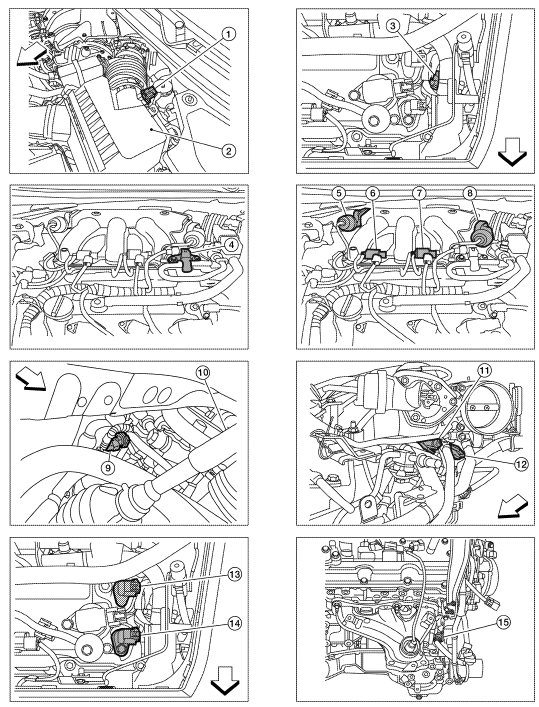
Component Parts Location
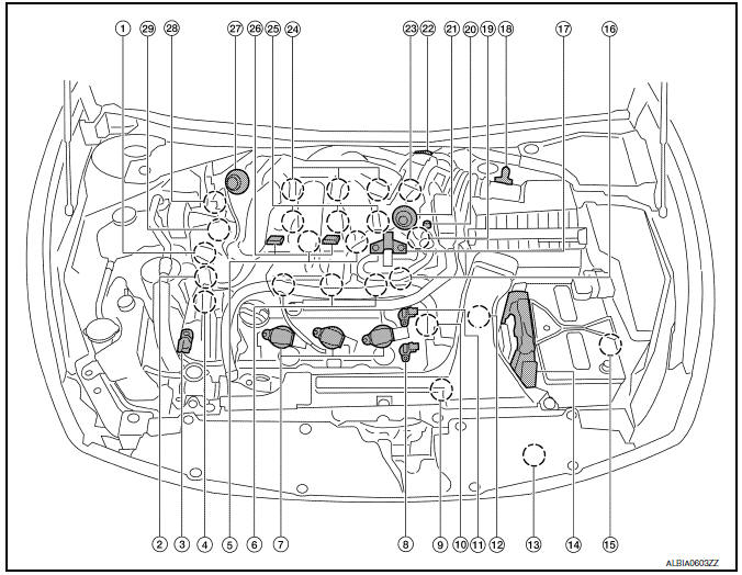
- Intake valve timing control solenoid valve (bank 1)
- Electronic controlled engine mount control solenoid valve
- Exhaust valve timing control magnet retarder (bank 2)
- Intake valve timing control solenoid valve (bank 2)
- Knock sensor (bank 1 and 2)
- Fuel injector (bank 2)
- Ignition coil (with power transistor) and spark plug (bank 2)
- Exhaust valve timing control position sensor (bank 2)
- Crankshaft position sensor (POS)
- Engine coolant temperature sensor
- Camshaft position sensor (PHASE) (bank 2)
- Transmission range switch
- Refrigerant pressure sensor
- ECM
- Battery current sensor
- Condenser-2
- EVAP canister purge volume control solenoid valve
- Mass air flow sensor (with intake air temperature sensor)
- Camshaft position sensor (PHASE) (bank 1)
- EVAP service port
- Power valve actuator 2
- Electric throttle control actuator
- Exhaust valve timing control position sensor (bank 1)
- Ignition coil (with power transistor) and spark plug (bank 1)
- Fuel injector (bank 1)
- VIAS control solenoid valve 1 and 2
- Power valve actuator 1
- Exhaust valve timing control magnet retarder (bank 1)
- Power steering pressure sensor
- Mas air flow sensor (with intake air temperature sensor)
- Air cleaner case
- Engine coolant temperature sensor (view with engine cover removed)
- EVAP canister purge volume control solenoid valve (view with engine cover removed)
- Power valve actuator 1 (view with engine cover removed)
- VIAS control solenoid valve 1
- VIAS control solenoid valve 2
- Power valve actuator 2
- Power steering pressure sensor
- Tie rod (RH)
- Camshaft position sensor (PHASE) (bank 1) (view with air cleaner case removed)
- Exhaust valve timing control position sensor (bank 1)
- Camshaft position sensor (PHASE) (bank 2) (view with air cleaner case removed)
- Exhaust valve timing control position sensor (bank 2)
- Engine oil temperature sensor
 : Vehicle front
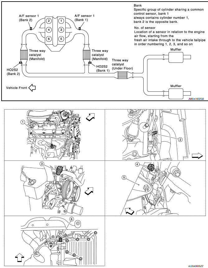
- A/F sensor 1 (bank 1) (view with engine removed)
- A/F sensor 1 (bank 2)
- HO2S2 (bank 1) harness connector (view with engine removed)
- HO2S2 (bank 2) harness connector
- Front engine mount
- Crankshaft position sensor (POS)
 : Vehicle front
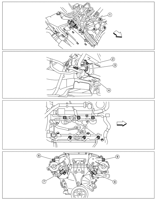
- Electronic controlled engine mount control solenoid valve (view with engine cover removed)
- EVAP control system pressure sensor (view with rear suspension member removed)
- EVAP canister vent control valve
- EVAP canister
- Fuel injector harness connector (view with intake manifold collector removed)
- Exhaust valve timing control magnet retarder (bank 1) (view with engine removed)
- Intake valve timing control solenoid valve (bank 1)
- Intake valve timing control solenoid valve (bank 2)
- Exhaust valve timing control magnet
retarder (bank 2)
 : Vehicle front
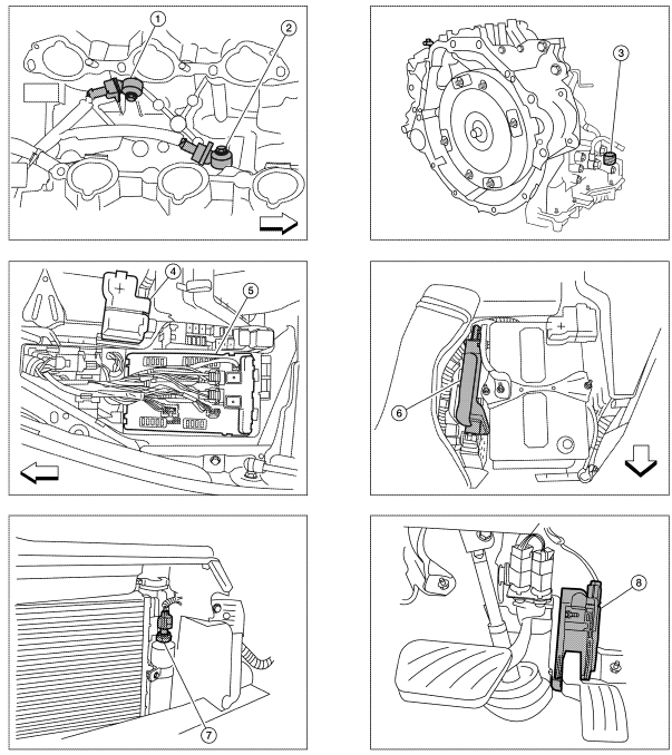
- Knock sensor (bank 2) (view with intake manifold removed)
- Knock sensor (bank 1)
- Transmission range switch (view with CVT removed)
- Battery
- IPDM E/R
- ECM
- Refrigerant pressure sensor (view with front grille removed)
- Accelerator pedal position sensor
 : Vehicle front
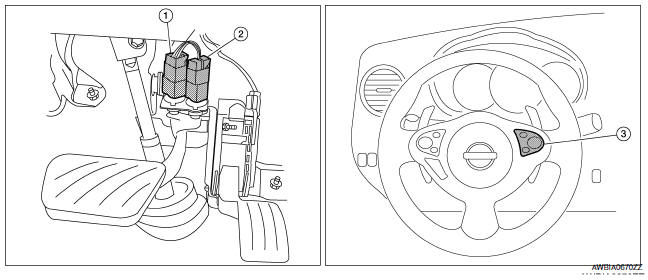
- Stop lamp switch
- ASCD brake switch
- ASCD steering switch
Component Description
Component Reference
- Camshaft position sensor EC-300, "Description"
- Crankshaft position sensor EC-296, "Description"
- Engine oil temperature sensor EC-277, "Description"
- Exhaust valve timing control magnet retarder EC-180, "Description"
- Exhaust valve timing control position sensor
 Evaporative emission system
System Diagram
System Description
*1: ECM determines the start signal status by the signals of engine speed and
battery voltage.
*2: This signal is sent to the ECM via the CAN communicat ...
 Intake valve timing control
System Diagram
System Description
INPUT/OUTPUT SIGNAL CHART
*: This signal is sent to the ECM via the CAN communication line
SYSTEM DESCRIPTION
This mechanism hydraulically controls c ...
Other materials:
Turning the FEB system on/off
Perform the following steps to turn the FEB systems
ON or OFF.
1. Press the button until
"Settings" displays
in the vehicle information display and
then press OK button. Use the
button
to select "Driver Assistance". Then press the
OK button.
2. Select "Emergency Brake" ...
Diagnosis system (BCM)
CONSULT Function (BCM - COMMON ITEM)
APPLICATION ITEM
CONSULT performs the following functions via CAN communication with BCM.
SYSTEM APPLICATION
BCM can perform the following functions.
CONSULT Function (BCM - AIR PRESSURE MONITOR)
NOTE: The Signal Tech II Tool (J-50190) can be used
to ...
Wiring diagram
AIR CONDITIONER CONTROL
Wiring Diagram - With Monochrome Display
...
Nissan Maxima Owners Manual
- Illustrated table of contents
- Safety-Seats, seat belts and supplemental restraint system
- Instruments and controls
- Pre-driving checks and adjustments
- Monitor, climate, audio, phone and voice recognition systems
- Starting and driving
- In case of emergency
- Appearance and care
- Do-it-yourself
- Maintenance and schedules
- Technical and consumer information
Nissan Maxima Service and Repair Manual

0.0074