Nissan Maxima Service and Repair Manual: Evaporative emission system
System Diagram
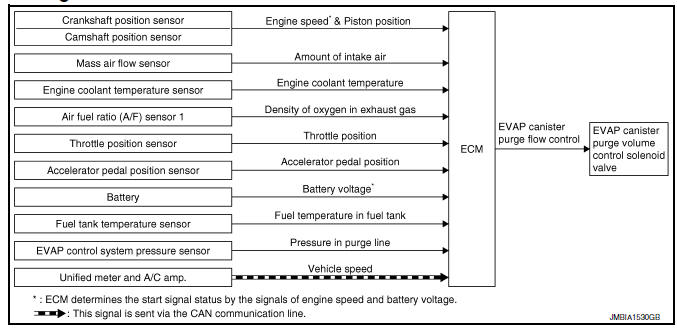
System Description
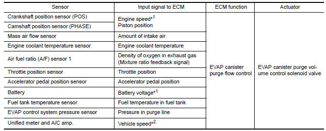
*1: ECM determines the start signal status by the signals of engine speed and
battery voltage.
*2: This signal is sent to the ECM via the CAN communication line.
SYSTEM DESCRIPTION
The evaporative emission system is used to reduce hydrocarbons emitted into the atmosphere from the fuel system. This reduction of hydrocarbons is accomplished by activated charcoals in the EVAP canister.
The fuel vapor in the sealed fuel tank is led into the EVAP canister which contains activated carbon and the vapor is stored there when the engine is not operating or when refueling to the fuel tank.
The vapor in the EVAP canister is purged by the air via the purge line to the intake manifold when the engine is operating. EVAP canister purge volume control solenoid valve is controlled by ECM. When the engine operates, the flow rate of vapor controlled by EVAP canister purge volume control solenoid valve is proportionally regulated as the air flow increases.
EVAP canister purge volume control solenoid valve also shuts off the vapor purge line during decelerating and idling.
EVAPORATIVE EMISSION LINE DRAWING
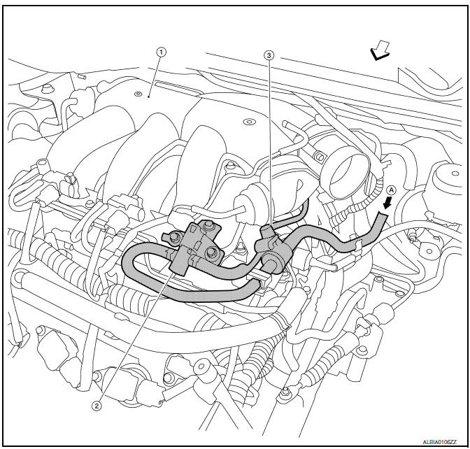
- Intake manifold collector
- EVAP canister purge volume control solenoid valve
- EVAP service port
- From EVAP canister
 : Vehicle front
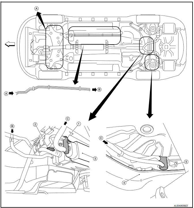
- EVAP canister vent control valve
- EVAP canister system pressure sensor
- EVAP canister
- Rear suspension member
- Drain filter
 : Front
 : Previous/next figure
NOTE: Do not use soapy water or any type of solvent while installing vacuum hose or purge hoses.
Component Parts Location
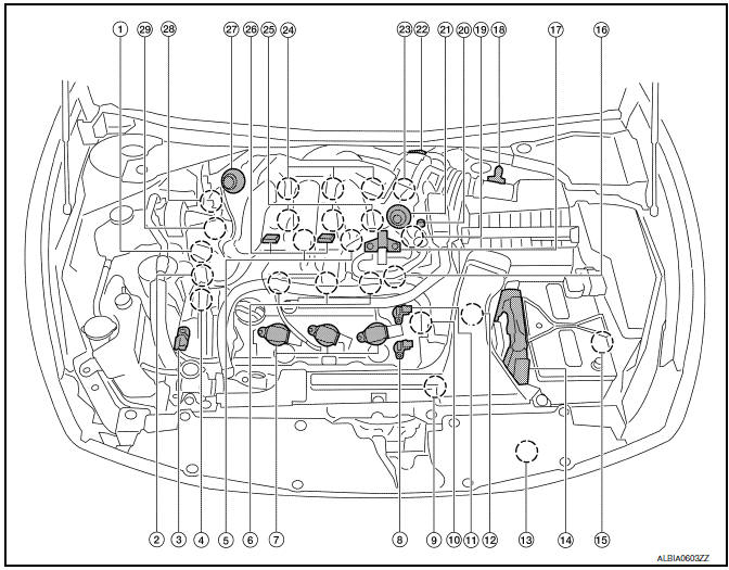
- Intake valve timing control solenoid valve (bank 1)
- Electronic controlled engine mount control solenoid valve
- Exhaust valve timing control magnet retarder (bank 2)
- Intake valve timing control solenoid valve (bank 2)
- Knock sensor (bank 1 and 2)
- Fuel injector (bank 2)
- Ignition coil (with power transistor) and spark plug (bank 2)
- Exhaust valve timing control position sensor (bank 2)
- Crankshaft position sensor (POS)
- Engine coolant temperature sensor
- Camshaft position sensor (PHASE) (bank 2)
- Transmission range switch
- Refrigerant pressure sensor
- ECM
- Battery current sensor
- Condenser-2
- EVAP canister purge volume control solenoid valve
- Mass air flow sensor (with intake air temperature sensor)
- Camshaft position sensor (PHASE) (bank 1)
- EVAP service port
- Power valve actuator 2
- Electric throttle control actuator
- Exhaust valve timing control position sensor (bank 1)
- Ignition coil (with power transistor) and spark plug (bank 1)
- Fuel injector (bank 1)
- VIAS control solenoid valve 1 and 2
- Power valve actuator 1
- Exhaust valve timing control magnet retarder (bank 1)
- Power steering pressure sensor
- Mas air flow sensor (with intake air temperature sensor)
- Air cleaner case
- Engine coolant temperature sensor (view with engine cover removed)
- EVAP canister purge volume control solenoid valve (view with engine cover removed)
- Power valve actuator 1 (view with engine cover removed)
- VIAS control solenoid valve 1
- VIAS control solenoid valve 2
- Power valve actuator 2
- Power steering pressure sensor
- Tie rod (RH)
- Camshaft position sensor (PHASE) (bank 1) (view with air cleaner case removed)
- Exhaust valve timing control position sensor (bank 1)
- Camshaft position sensor (PHASE) (bank 2) (view with air cleaner case removed)
- Exhaust valve timing control position sensor (bank 2)
- Engine oil temperature sensor
 : Vehicle front
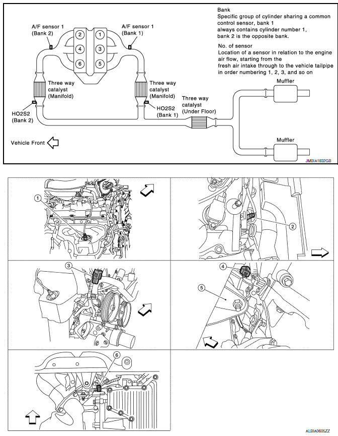
- A/F sensor 1 (bank 1) (view with engine removed)
- A/F sensor 1 (bank 2)
- HO2S2 (bank 1) harness connector (view with engine removed)
- HO2S2 (bank 2) harness connector
- Front engine mount
- Crankshaft position sensor (POS)
 : Vehicle front
- Electronic controlled engine mount control solenoid valve (view with engine cover removed)
- EVAP control system pressure sensor (view with rear suspension member removed)
- EVAP canister vent control valve
- EVAP canister 5. Fuel injector harness connector (view with intake manifold collector removed)
- Exhaust valve timing control magnet retarder (bank 1) (view with engine removed)
- Intake valve timing control solenoid valve (bank 1)
- Intake valve timing control solenoid valve (bank 2)
- Exhaust valve timing control magnet
retarder (bank 2)
 : Vehicle front
- Knock sensor (bank 2) (view with intake manifold removed)
- Knock sensor (bank 1)
- Transmission range switch (view with CVT removed)
- Battery
- IPDM E/R
- ECM
- Refrigerant pressure sensor (view with front grille removed)
- Accelerator pedal position sensor
 : Vehicle front
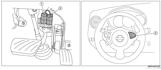
- Stop lamp switch
- ASCD brake switch
- ASCD steering switch
Component Description
Component Reference
- A/F sensor 1 EC-218, "Description"
- Accelerator pedal position sensor EC-467, "Description"
- Camshaft position sensor (PHASE) EC-300, "Description"
- Crankshaft position sensor (POS) EC-296, "Description"
- Engine coolant temperature sensor EC-201, "Description"
- EVAP canister purge volume control solenoid valve EC-323, "Description"
- EVAP control system pressure sensor EC-343, "Description"
- Fuel tank temperature sensor EC-269, "Description"
- Mass air flow sensor EC-183, "Description" Throttle position senso
 Electronic controlled engine mount
System Diagram
System Description
INPUT/OUTPUT SIGNAL CHART
*: This signal is sent to the ECM via the CAN communication line.
SYSTEM DESCRIPTION
The ECM controls the engine mount operatio ...
 Exhaust valve timing control
System Diagram
System Description
INPUT/OUTPUT SIGNAL CHART
*: This signal is sent to the ECM via the CAN Communication line.
SYSTEM DESCRIPTION
This mechanism magnetically controls c ...
Other materials:
Bose speaker AMP\
Removal and Installation
Bose speaker amp.
Screws
REMOVAL
NOTE:
If removing the BOSE speaker amp. bracket, it is necessary to remove the parcel
shelf finisher. The BOSE
speaker amp. can be removed without removing the BOSE speaker amp. bracket.
Disconnect the battery negativ ...
Power window serial link
POWER WINDOW MAIN SWITCH
POWER WINDOW MAIN SWITCH : Description
Main power window and door lock/unlock switch, power window and door
lock/unlock switch RH and BCM
communicate via the power window serial link.
The keyless power window down signal is transmitted from BCM to
main power ...
Opening the trunk lid
1. Push the trunk opener request switch A for
more than 1 second while carrying the Intelligent
Key with you. If all doors are already
unlocked, opening the trunk does NOT require
an Intelligent Key to be in range of the
trunk opener request switch or rear of the
vehicle.
2. The trunk w ...
Nissan Maxima Owners Manual
- Illustrated table of contents
- Safety-Seats, seat belts and supplemental restraint system
- Instruments and controls
- Pre-driving checks and adjustments
- Monitor, climate, audio, phone and voice recognition systems
- Starting and driving
- In case of emergency
- Appearance and care
- Do-it-yourself
- Maintenance and schedules
- Technical and consumer information
Nissan Maxima Service and Repair Manual

0.0068