Nissan Maxima Service and Repair Manual: Harness connector
Description
HARNESS CONNECTOR (TAB-LOCKING TYPE)
- The tab-locking type connectors help prevent accidental looseness or disconnection.
- The tab-locking type connectors are disconnected by pushing or
lifting the locking tab(s). Refer to the figure
below.
Refer to the next page for description of the slide-locking type connector.
CAUTION: Do not pull the harness or wires when disconnecting the connector.
[Example]
HARNESS CONNECTOR (SLIDE-LOCKING TYPE)
- A new style slide-locking type connector is used on certain systems and components, especially those related to OBD.
- The slide-locking type connectors help prevent incomplete locking and accidental looseness or disconnection.
- The slide-locking type connectors are disconnected by pushing or pulling the slider. Refer to the figure below.
CAUTION:
- Do not pull the harness or wires when disconnecting the connector.
- Be careful not to damage the connector support bracket when disconnecting the connector.
[Example]
HARNESS CONNECTOR (LEVER LOCKING TYPE)
- Lever locking type harness connectors are used on certain control units and control modules such as ECM, ABS actuator and electric unit (control unit), etc.
- Lever locking type harness connectors are also used on super multiple junction (SMJ) connectors.
- Always confirm the lever is fully locked in place by moving the lever as far as it will go to ensure full connection.
CAUTION:
- Always confirm the lever is fully released (loosened) before attempting to disconnect or connect these connectors to avoid damage to the connector housing or terminals.
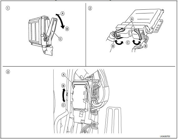
- Control unit with single lever
A. Fasten
B. Loosen
C. Lever - Control unit with dual lever
A. Levers
B. Fasten
C. Loosen - SMJ connector
A. Lever
B. Fasten
C. Loosen
HARNESS CONNECTOR (DIRECT-CONNECT SRS COMPONENT TYPE)
- SRS direct-connect type harness connectors are used on certain SRS components such as air bag modules and seat belt pre-tensioners.
- Always pull up to release black locking tab prior to removing connector from SRS components.
- Always push down to lock black locking tab after installing connector to SRS components. When locked, the black locking tab is level with the connector housing.
CAUTION:
- Do not pull the harness or wires when removing connectors from SRS components.
 Electrical units location
Electrical Units Location
ENGINE COMPARTMENT
PASSENGER COMPARTMENT
LUGGAGE COMPARTMENT
...
 Standardized relay
Description
NORMAL OPEN, NORMAL CLOSED AND MIXED TYPE RELAYS
Relays can mainly be divided into three types: normal open, normal closed and
mixed type relays
TYPE OF STANDARDIZED RELAYS
1M * ...
Other materials:
Inspection and adjustment
ECM RE-COMMUNICATING FUNCTION
ECM RE-COMMUNICATING FUNCTION : Description
the ECM has been replaced with a new one (*1).
*1: New one means an ECM which has never been energized on-board.
(In this step, initialization procedure by CONSULT is not necessary)
NOTE:
When registering new Key ...
Water outlet and water piping
Removal and Installation
Heater hose
Clamp
Water hose
Clamp
Water outlet
Gasket
Gasket
Water connector
O-ring
Water bypass pipe
Clamp
Water hose
Heater pipe
Water hose
Heater hose
Engine coolant temperature sensor
Clamp
Radiator hose (upper)
&n ...
Fuel level sensor signal circuit
Description
The fuel level sensor unit and fuel pump (fuel level
sensor) detects the approximate fuel level in the fuel tank
and transmits the fuel level signal to the combination meter.
Component Function Check
1.COMBINATION METER INPUT SIGNAL
Select "METER/M&A" on CONSULT.
...
Nissan Maxima Owners Manual
- Illustrated table of contents
- Safety-Seats, seat belts and supplemental restraint system
- Instruments and controls
- Pre-driving checks and adjustments
- Monitor, climate, audio, phone and voice recognition systems
- Starting and driving
- In case of emergency
- Appearance and care
- Do-it-yourself
- Maintenance and schedules
- Technical and consumer information
Nissan Maxima Service and Repair Manual

0.0064