Nissan Maxima Service and Repair Manual: Basic inspection
DIAGNOSIS AND REPAIR WORKFLOW
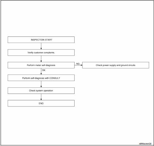
Work Flow
OVERALL SEQUENCE
DETAILED FLOW
1.CONFIRM SYMPTOM
Confirm symptom or customer complaint.
2.CHECK SELF-DIAGNOSIS OPERATION OF COMBINATION METER
Perform self-diagnosis of combination meter. Refer to MWI-29, "Diagnosis Description".
3.CHECK COMBINATION METER (CONSULT)
Select "METER/M&A" on CONSULT and perform "SELF-DIAGNOSIS" of combination meter. Refer to MWI- 29, "CONSULT Function (METER/M&A)".
4.CONFIRM OPERATION


Other materials:
U1000 CAN comm circuit
Description
CAN (Controller Area Network) is a serial communication line for real time
application. It is an on-vehicle multiplex
communication line with high data communication speed and excellent error
detection ability. Many electronic
control units are equipped onto a vehicle, and each ...
SRS air bag system
"AIR BAG" Warning Lamp Does Not Turn Off
DIAGNOSTIC PROCEDURE
1.CHECK CONDITION OF AIR BAG MODULE
Inspect for any deployed air bag modules or seat belt pre-tensioners.
2.CHECK THE AIR BAG FUSE
Check 10A fuse [No. 2, located in the fuse block (J/B)].
3.CHECK AIR BAG FUSE AGAIN
Replace 10A fuse ...
Continuously Variable Transmission (CVT) fluid
CAUTION
NISSAN recommends using Genuine
NISSAN CVT Fluid NS-3 (or equivalent)
ONLY in NISSAN CVTs. Do not mix with
other fluids.
Do not use Automatic Transmission
Fluid (ATF) or Manual transmission
fluid in a NISSAN CVT, as it may damage
the CVT. Damage caused by the use of
fluid ...
Nissan Maxima Owners Manual
- Illustrated table of contents
- Safety-Seats, seat belts and supplemental restraint system
- Instruments and controls
- Pre-driving checks and adjustments
- Monitor, climate, audio, phone and voice recognition systems
- Starting and driving
- In case of emergency
- Appearance and care
- Do-it-yourself
- Maintenance and schedules
- Technical and consumer information
Nissan Maxima Service and Repair Manual

0.0061