Nissan Maxima Service and Repair Manual: Front combination lamp
Exploded View
- Front combination lamp
Removal and Installation
FRONT COMBINATION LAMP
Removal
CAUTION: Disconnect the battery negative terminal or remove the fuse.
- Remove the front bumper fascia. Refer to EXT-16, "Removal and Installation".
- Remove the front combination lamp bolts.
- Remove the harness clips from the front combination lamp assembly.
- Pull out the front combination lamp toward the front of vehicle.
- Disconnect the harness connectors from the front combination lamp and remove.
Installation
Installation is in the reverse order of removal.
NOTE: After installation, perform headlamp aiming adjustment. Refer to EXL-150, "Description".
XENON BULB
Removal
WARNING: Do not touch bulb with your hand while it is on or right after being turned off, a burn injury may result.
CAUTION:
- After installing the bulb, install the plastic cover and the bulb socket securely for watertightness.
- Do not touch bulb glass with your hand or keep other grease and oily substances away from bulb glass.
- Do not leave bulb out of lamp reflector for a long time because dust, moisture smoke, etc. may affect the performance of lamp. When replacing bulb, be sure to replace it with new one.
- Disconnect the battery negative terminal or remove the fuse.
- Remove the front combination lamp. Refer to EXL-154, "Removal and Installation".
- Remove screw from cover and rotate the plastic cover counterclockwise and unlock from the front combination lamp.
- Rotate the xenon bulb socket counterclockwise and unlock from the front combination lamp.
- Unlock the retaining spring and remove the xenon bulb from the front combination lamp.
CAUTION: Do not break the xenon bulb ceramic tube when replacing the bulb.
Installation
Installation is in the reverse order of removal.
HALOGEN BULB (HIGH BEAM)
Removal
- Remove the front combination lamp. Refer to EXL-154, "Removal and Installation".
- Rotate the bulb socket counterclockwise and unlock from the front combination lamp.
- Remove the bulb from the bulb socket.
Installation
Installation is in the reverse order of removal.
FRONT TURN SIGNAL LAMP BULB
Removal
- Remove the front combination lamp. Refer to EXL-154, "Removal and Installation".
- Rotate the bulb socket counterclockwise and unlock from the front combination lamp.
- Remove the bulb from the bulb socket.
Installation
Installation is in the reverse order of removal.
FRONT SIDE MARKER LAMP BULB
Removal
- Remove the front combination lamp. Refer to EXL-154, "Removal and Installation".
- Rotate the bulb socket counterclockwise and unlock from the front combination lamp.
- Remove the bulb from the bulb socket.
Installation
Installation is in the reverse order of removal.

 Front fog lamp
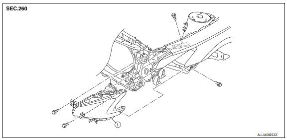
Exploded View
Front bumper fascia
Front fog lamp
Front fog lamp bracket
Clip
Spring nuts
Removal and Installation
FRONT FOG LAMP
Removal
Remove the front bumper fascia. Refer ...
Other materials:
Front sunroof glass
Removal and Installation
REMOVAL
Remove the wind deflector. Refer to RF-168, "Removal and
Installation".
Tape down the glass lid weatherstrip along the from sunroof glass
with protective tape.
Apply protective tape around the front sunroof glass to protect
the surface from damage.
...
B1086 - B1089 seat belt pre-tensioner LH
Description
DTC B1086 - B1089 SEAT BELT PRE-TENSIONER LH
The seat belt pre-tensioner LH is wired to the air bag diagnosis sensor unit.
The air bag diagnosis sensor unitwill monitor for opens and shorts in
detected lines to the seat belt pre-tensioner LH.
PART LOCATION
DTC Logic
DTC DETECTIO ...
Horn
Description
Horn (high/low) is located inside of front bumper and
operates when theft warning system is in alarm phase.
Component Function Check
1.CHECK FUNCTION
Select HORN in "ACTIVE TEST" mode with CONSULT.
Check the horn (high/low) operation.
Diagnosis Pro ...
Nissan Maxima Owners Manual
- Illustrated table of contents
- Safety-Seats, seat belts and supplemental restraint system
- Instruments and controls
- Pre-driving checks and adjustments
- Monitor, climate, audio, phone and voice recognition systems
- Starting and driving
- In case of emergency
- Appearance and care
- Do-it-yourself
- Maintenance and schedules
- Technical and consumer information
Nissan Maxima Service and Repair Manual

0.0052