Nissan Maxima Service and Repair Manual: Warning function
System Description
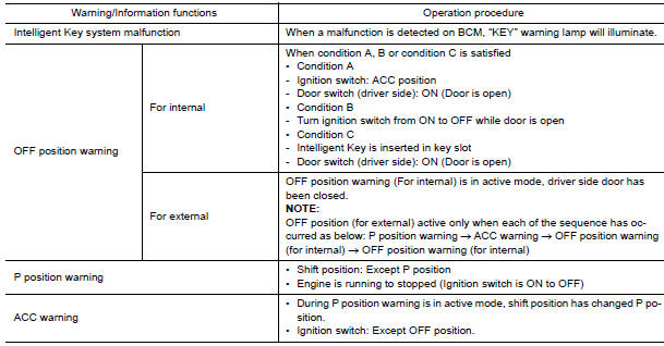
OPERATION DESCRIPTION
The warning functions are as follows and are given to the user as warning information and warnings using combinations of Intelligent Key warning buzzer, KEY warning lamp, key slot illumination and combination meter display in combination meter.
- Intelligent Key system malfunction
- OFF position warning
- P position warning
- ACC warning
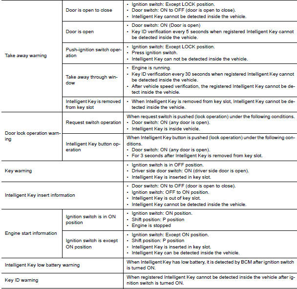
- Take away warning
- Door lock operation warning
- Key warning
- Intelligent Key insert information
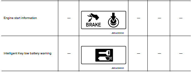
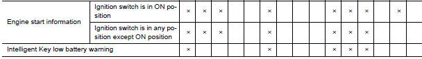
- Engine start information
- Intelligent Key low battery warning
- Key ID warning
OPERATION CONDITION
Once the following condition from below is established, alert or warning will be executed.
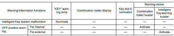
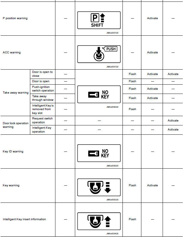
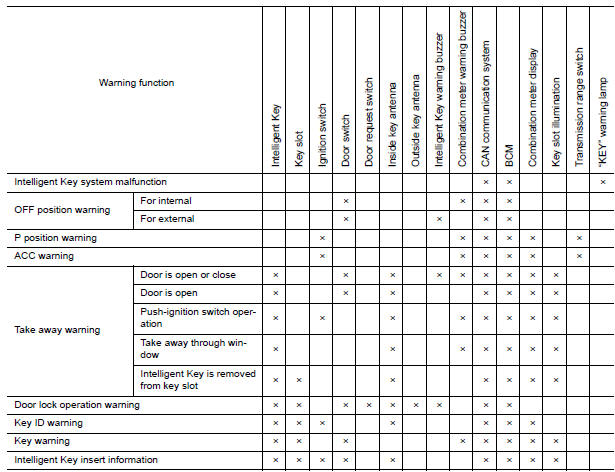
WARNING METHOD
The following table shows the alarm or warning methods with chime.
Meter display, "KEY" indicator or key slot illumination when the warning conditions are met.
LIST OF OPERATION RELATED PARTS
Parts marked with × are the parts related to operation.
Component Parts Location
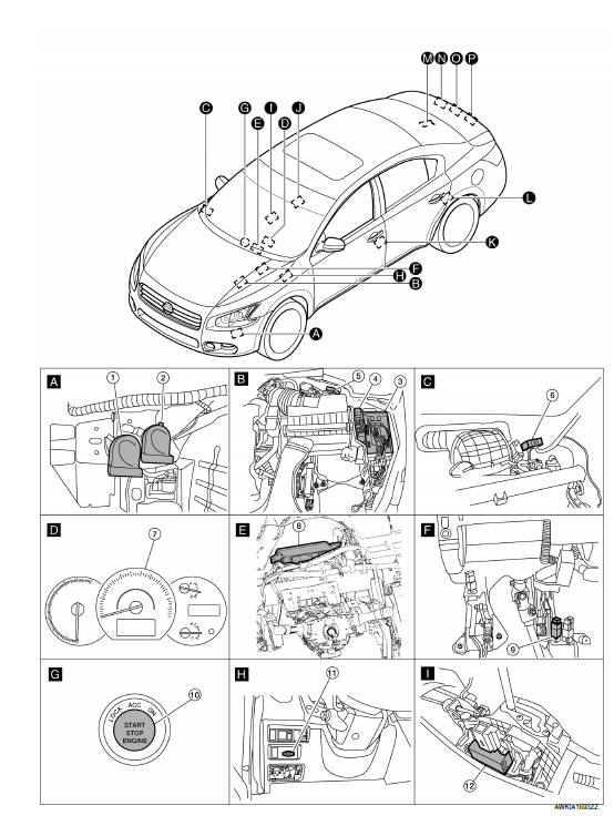
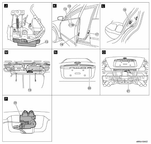
- Horn (low) E215 (view with front fender protector LH removed)
- Horn (high) E216
- IPDM E/R E17, E18
- Horn relay H-1
- Intelligent Key warning buzzer E28
- Remote keyless entry receiver M27 (view with instrument panel removed)
- Combination meter M24
- BCM M16, M17, M18, M19, M20, M21 (view with instrument panel removed)
- Stop lamp switch E38
- Push button ignition switch M38
- Key slot M40
- CVT shift selector (park position switch (Intelligent Key system)) M78
- Front console antenna M41 (view with center console assembly removed)
- Front outside handle LH (outside key
antenna) D6
Front outside handle RH (outside key antenna) D106 - Front outside handle LH (request
switch) D15
Front outside handle RH (request switch) D115 - Front door lock assembly LH (door unlock sensor) D10
- Front door switch LH B8 RH B108
- Rear door switch LH B18 RH B116
- Rear parcel shelf antenna B29
- Trunk opener request switch T5
- Rear bumper antenna B46
- Trunk lamp switch and trunk release solenoid T7
 Trunk open function
TRUNK LID OPENER SWITCH
TRUNK LID OPENER SWITCH : System Diagram
TRUNK LID OPENER SWITCH : System Description
TRUNK LID OPENER OPERATION
When trunk lid opener switch is ON, BCM opens trunk ...
 Key reminder function
System Description
Key reminder is the function that prevents the key from being left in the
vehicle.
Key reminder has the following 3 functions.
Key reminder function
Opera ...
Other materials:
Engine speed signal circuit
Description
ECM sends engine speed signal to power steering control unit.
Diagnosis Procedure
1.PERFORM ECM SELF-DIAGNOSIS
With CONSULT
Perform ECM self-diagnosis.
2.CHECK HARNESS BETWEEN ECM AND POWER STEERING CONTROL UNIT FOR OPEN
Turn the ignition switch OFF.
Disconnect ECM connec ...
Basic inspection
DIAGNOSIS AND REPAIR WORKFLOW
Work Flow
OVERALL SEQUENCE
DETAILED FLOW
1. GET INFORMATION FOR SYMPTOM
Get the detailed information from the customer about the symptom (the
condition and the environment when
the incident/malfunction occurred).
2. CHECK DTC
Check DTC.
Perform the f ...
Reclining sensor
Description
The reclining motor is installed to the seatback assembly.
The pulse signal is input to the driver seat control unit when the
reclining is operated.
The driver seat control unit counts the pulse and calculates the
reclining amount of the seat.
Component Function Check
1 ...
Nissan Maxima Owners Manual
- Illustrated table of contents
- Safety-Seats, seat belts and supplemental restraint system
- Instruments and controls
- Pre-driving checks and adjustments
- Monitor, climate, audio, phone and voice recognition systems
- Starting and driving
- In case of emergency
- Appearance and care
- Do-it-yourself
- Maintenance and schedules
- Technical and consumer information
Nissan Maxima Service and Repair Manual

0.0054