Nissan Maxima Service and Repair Manual: Engine speed signal circuit
Description
ECM sends engine speed signal to power steering control unit.
Diagnosis Procedure
1.PERFORM ECM SELF-DIAGNOSIS
With CONSULT
Perform ECM self-diagnosis.
2.CHECK HARNESS BETWEEN ECM AND POWER STEERING CONTROL UNIT FOR OPEN
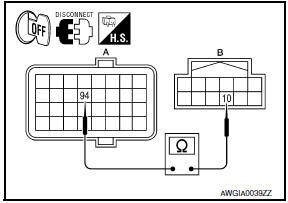
- Turn the ignition switch OFF.
- Disconnect ECM connector E10.
- Disconnect power steering control unit connector.
- Check continuity between ECM connector E10 (A) terminal 94
and power steering control unit connector M59 (B) terminal 10.
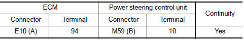
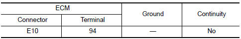
3.CHECK HARNESS BETWEEN ECM AND POWER STEERING CONTROL UNIT FOR SHORT
- Check continuity between ECM connector E10 terminal 94 and
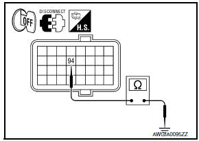
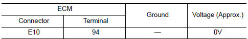
ground. - Turn ignition switch ON.
- Check voltage between ECM connector E10 terminal 94 and
ground.
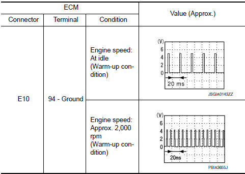
4.CHECK ENGINE SPEED SIGNAL (ECM SIDE)
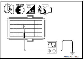
- Turn the ignition switch OFF.
- Connect ECM connector E10.
- Start the engine.
- Check signal between ECM connector E10 terminal 94 and
ground with oscilloscope.
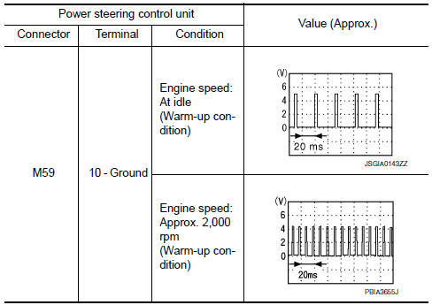
5.CHECK ENGINE SPEED SIGNAL (POWER STEERING CONTROL UNIT SIDE)
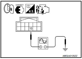
- Turn the ignition switch OFF.
- Connect power steering control unit harness connector.
- Start the engine.
- Check signal between power steering control unit harness connector
M59 terminal 10 and ground with oscilloscope
6.CHECK TERMINALS AND HARNESS CONNECTORS
- Check power steering control unit pin terminals for damage or loose connection with harness connector.
- Check ECM pin terminals for damage or loose connection with harness connector.
 Power steering solenoid valve
Description
Power steering solenoid valve controls the power steering oil pressure in the
gear housing assembly.
Diagnosis Procedure
1.CHECK POWER STEERING SOLENOID VALVE SIGNAL
Start eng ...
 Vehicle speed signal circuit
Description
Combination meter sends vehicle speed signal to power steering control unit.
Diagnosis Procedure
1.PERFORM COMBINATION METER SELF-DIAGNOSIS
Perform combination meter self-diagnosis.
2 ...
Other materials:
Locking doors
1. Move the shift lever to the P (Park) position,
place the ignition switch in the LOCK position
and make sure you carry the Intelligent
Key with you.
2. Close all doors.
3. Push any door handle request switch while
carrying the Intelligent Key with you.
4. All doors will lock.
5 ...
Precaution
Precaution for Supplemental Restraint System (SRS) "AIR BAG" and
"SEAT BELT PRE-TENSIONER"
The Supplemental Restraint System such as "AIR BAG" and "SEAT BELT
PRE-TENSIONER", used along with a front seat belt, helps to reduce the risk
or severity of injury to the driver and front passenger for ...
P1715 input speed sensor
Description
ECM receives input speed sensor signal from TCM via the CAN communication
line. ECM uses this signal for
engine control.
DTC Logic
DTC DETECTION LOGIC
NOTE:
If DTC P1715 is displayed with DTC UXXXX first perform the
trouble diagnosis for DTC UXXXX. Refer
to EC-161 ...
Nissan Maxima Owners Manual
- Illustrated table of contents
- Safety-Seats, seat belts and supplemental restraint system
- Instruments and controls
- Pre-driving checks and adjustments
- Monitor, climate, audio, phone and voice recognition systems
- Starting and driving
- In case of emergency
- Appearance and care
- Do-it-yourself
- Maintenance and schedules
- Technical and consumer information
Nissan Maxima Service and Repair Manual

0.0078